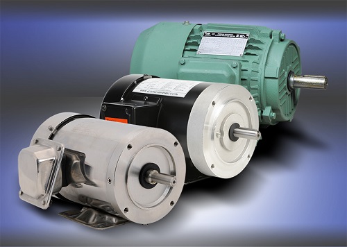
Most automatic controls involve AC motor control in some way, especially in factory automation. Applications such as pumps, fans, robotics, and conveyors use motors. Whether general-purpose 3-phase ac motors, which are great for simple on/off systems, or the inverter-duty motors specifically designed for operation with variable frequency drives (VFDs), one could say that motors are ubiquitous in nearly all manufacturing industries. Check out the different types of AC motor control options available.
AC Motor Control Options
While there are different motor types for different situations, motor sizes vary to accommodate varying loads. And with varying motor sizes comes varying motor-starting scenarios. Small general-purpose motors typically are connected to the main power circuit with a master circuit breaker or fuses. Contactors enable and disable the power to the motor while overloads protect the motor-driven equipment from unexpected overcurrent/overheating that can be caused by jams or breakdowns.
Starting AC Motors Across-the-Line
As the name implies, an across-the-line motor starter applies full voltage, current, and torque immediately to the motor when the circuit is energized. In industry, a motor starter is the most common method of across-the-line motor starting. Typically, a motor starter consists of a contactor to open or close the flow of energy to the motor, and an overload relay to protect the motor from thermal overload.
A contactor is a 3-pole electromechanical switch whose contacts are closed by applying voltage to a coil, much like a relay. When the coil is energized, the contacts are closed, and remain closed until the coil is de-energized. Because motors are inductive devices, breaking the current (magnetizing, or motor and torque-producing, or load) is more difficult than applying it. Therefore, the contactor must be rated for both horsepower and current.
The overload relay has three current-sensing elements that protect the motor from an overcurrent—one for each phase. If the overload current exceeds the setting of the relay for a sufficient length of time, a set of contacts opens to protect the motor from damage.
Reversing starters reverse the shaft rotation of a 3-phase motor by interchanging two of the phases that supply the motor. Reversing magnetic motor starters feature a forward and a reverse contactor as part of the assembly. Electrical and mechanical interlocks are provided to ensure only the forward or the reverse contactor can be engaged at any given time, but not at the same time.
Typically, AC motor starter circuits can be controlled from simple pushbuttons or from remote signals such as from a programmable logic controller (PLC).
Across-the-line motor starting is used when the application can run at the motor’s maximum speed and when speed and voltage sags/spikes don’t pose a problem. Motor starters are commonly used with smaller motors where users don’t need the electrical and mechanical softening effects of a soft starter.
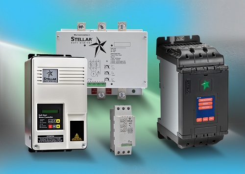
Soft Starters Minimize Electrical, Mechanical Impact
There are electrical and mechanical advantages to using a soft starter. When a motor is started across-the-line, the sudden impact of going from 0 rpm to full speed of 1,800 or 3,600 rpm is felt mechanically down the line through the connected mechanical load, and typically draws six to 10 times full load amps (FLA) in current. Soft starters can reduce the load on the motor, the electrical current it uses, and the shock to downstream machinery. Electrically, it makes no difference to the utility when starting a 1 hp motor across-the-line. But there is still some mechanical shock to downstream equipment. However, starting a 300 hp motor across-the-line will get the power company’s attention. Demand charges may result from spikes occurring at the wrong time of day. The larger motor imposes an even greater mechanical impact on downstream equipment Using a soft starter provides the benefits of not damaging the machinery downstream and the power company doesn’t impose charges for these huge peak inrush currents.
A soft starter uses voltage to control the current and torque. Motor torque is proportional to the square of the applied voltage. The current during starting is directly related to the voltage applied to the motor. In most soft starters, three pairs of back-to-back silicon-controlled rectifiers (SCRs) are used to start and stop the motor, which correspond to the three motor phases. The back-to-back orientation of the SCRs allows the ac voltage to be controlled by changing the firing angle every half cycle. Voltage is either ramped up to full voltage, or is limited to provide current limited starts.
When the motor reaches operating speed, the bypass contactor is pulled in. Whether it’s an internal bypass or an external bypass, the SCRs stop firing, which makes the soft starter more efficient. After a motor stop command is provided, the SCRs again take control from the bypass contactor for the stop. The contactor never makes or breaks a load, which allows smaller contactors and SCRs to be used.
Soft starters can be between 99.5% to 99.9% efficient. Typically, less than 1 V is dropped across an SCR pair. Efficiency depends on the size of the soft starter and the 3-phase voltage applied. In some cases, after the starting process is complete, a soft start with integrated bypass pulls in an internal bypass contactor. The SCRs are no longer firing and all running current is across the contacts. When operating at full speed and properly loaded, soft starters are more efficient than VFDs, yet unlike VFDs, cannot control the speed of the motor.
Soft starters are used where both electrical and mechanical impact of motor starting must be minimized. With smaller motors, it’s more about protecting downstream machines from mechanical shock. With larger motors, in addition to protecting equipment, it’s minimizing demand charges.
Soft starters are commonly used with conveyors, pumps, fans, and blowers. Unlike with VFDs, users don’t have to worry about generating harmonics. However, soft starters don’t have speed control.
Controlling speed, saving energy with VFDs
VFDs are best where speed control is a factor, and energy efficiency is important. VFDs control an ac motor’s speed and torque by adjusting the input frequency and voltage to 3-phase ac induction, permanent magnet (interior or surface), or synchronous motors. VFDs also provide overload protection, start/stop control, and adjustable acceleration/deceleration. Programmable acceleration and processor-controlled current limiting can reduce motor inrush current at startup.
When specifying a VFD, it’s important to understand the application and select the drive accordingly. The operating profile of the load must first be considered. With both constant torque applications, such as conveyors, mixers, and compressors—and variable torque applications, such as pumps, fans, and blowers—careful attention must be paid to overload ratings. For example, attempting to drive a fan motor faster than its base speed can significantly impact the amount of power required because the fan horsepower varies with the cube of the speed. Running a fan too fast can consume excess power and may overload the VFD, while running it at half speed can reduce horsepower requirements by 75% or more, per the affinity laws, which apply to pumps and fans.
A VFD converts ac line voltage to dc voltage, filters it, and then inverts the it back into a usable signal. The RMS value of the inverted signal simulates an ac voltage. The output frequency of the VFD usually is from 0 Hz to the ac input line frequency. However, higher frequencies also are possible when required for certain applications. Many ac drives historically used a full-wave diode bridge or SCR rectifier bridge in the converter section to convert the ac source to dc voltage. However, VFDs with insulated-gate bipolar transistors (IGBTs) are now used. The filter section, primarily a capacitor bank, smooths out the rapidly-switched dc voltage produced from the converter.
A choke or inductor can be added to improve power factor and reduce harmonics. The smoothed-out dc voltage is then used by the IGBT inverter. The fast-acting switching from the inverter section generates the proper RMS simulated ac voltage levels, also known as a pulse width modulated (PWM) waveform. Older IGBT drives were 6-pulse. However, 12-pulse and 18-pulse VFDs are now available.
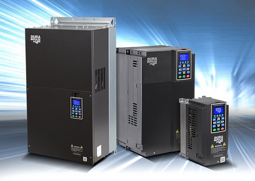
Modern VFDs, such as the line of DURApulse GS4 AC drives from AutomationDirect, are feature-rich. For example, one of the biggest features of the GS4 is the built-in fully-functional PLC, which enables users to program drive-related logic requirements, such as controlling multiple pumps. Other features include multiple high-speed communication interfaces and a 100-kA short circuit current rating (SCCR).
VFDs offer the same benefits as do soft starters with the added benefit of speed control. A motor is most efficient when loaded between 80% and 100%. An oversized motor is less efficient than a properly sized motor, but a VFD helps to minimize this inefficiency, reducing the oversizing penalty to little more than the initial cost for oversizing the drive and motor. Drives typically are 95% to 98% efficient. The higher number of pulses in the drive, the higher the efficiency. For example, a 6-pulse drive is 96.5% to 97.5% efficient. An 18-pulse drive is 97.5% to 98% efficient.
To read more articles about motors, click here.