

Reliable off-the-shelf automation components can accelerate the development of prototype projects and ready them for scale-up.
By: David Powell
The shipbuilding industry—where lead times for new vessels often stretch into years and repairs are time and safety critical—often requires large, specialized parts, which are costly and time consuming to manufacture with conventional methods. For this reason, the maritime industry is increasingly pursuing novel manufacturing techniques to obtain parts, as an alternative to the traditional supply chain. One approach is to use additive manufacturing techniques, such as wire arc additive manufacturing (WAAM), to produce large-scale metal parts.
WAAM allows complex parts to be quickly constructed on-site, and perhaps even on board in the future, reducing both lead times and supply chain complexity. However, the adoption of WAAM is stymied by the drawbacks of closed-source systems currently available, including high costs and the risk of becoming dependent on a single ecosystem.
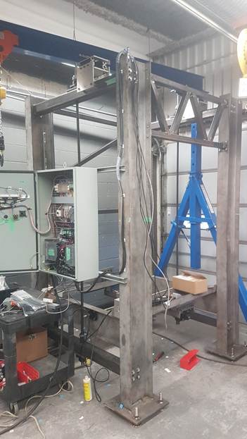
In response to this problem, a shipbuilder approached the Centre for Applied Research & Innovation (CARI) at the British Columbia Institute of Technology (BCIT), looking to support development of an open-source WAAM system (Figure 1). Our team of three students and engineers from BCIT and Simon Fraser University (SFU) rose to address the challenge and gain hands-on experience unlike anything possible in the classroom. Achieving the development of a cutting-edge system is an ambitious target for a group of students, and with an 18-month timeline, the team quickly realized they would need to rely on proven, industry-standard hardware and software motion control solutions.
Super-Sizing a 3D Printer
Wire arc additive manufacturing can be compared to a combination of welding and fused deposition modeling (FDM), a technique commonly used on polymer 3D printers where parts are constructed layer by layer. In WAAM, metal filament is melted by an automated welding arm using high-powered electric arcs. This molten metal is then deposited one layer at a time, allowing complex parts to be constructed quickly, with minimal post-processing required. Unlike other forms of metal additive manufacturing, such as powder bed fusion (PBF) or metal FDM, WAAM allows for significantly larger part geometries, at the expense of surface finish and part tolerance. However, for maritime applications, the large build volume of WAAM is crucial, while the lower accuracy and rougher surface finish are less critical.
For the design, our team settled on a gantry system providing three axes of motion, with one vertical (Z) and two horizontal (X/Y) axes. The welding arm is mounted on a gantry, which moves in the horizontal plane, allowing access to the entire surface of the print. The part itself is fused to a large bed. To build depth, the bed is lowered away from the gantry arm as the height of the part increases with each layer.
Controlling and synchronizing motion across all three axes is already a complex problem. However, the team faced the added challenge of designing the machine to handle the large volume and heavy weight of the parts, while providing sufficient speed control to perform high-quality welds. Furthermore, the automation would need to stand up to harsh physical and electro-magnetic interference conditions.
In addition to the motion requirements, the team needed to consider the machine workflow. An important requirement was that the machine support g-code, which is an industry-standard programming language commonly used on computer numerical control (CNC) machines and 3D printers. A variety of both open and closed-source platforms are available to facilitate g-code generation. G-code provides the machine with a sequence of coordinates and directives, telling it where to travel and how quickly to move, while controlling actions such as heating, welding, and material deposition rate.
Automating Industrial Reliability
While desktop 3D printers use a variety of microcontrollers, many of them consumer-grade, this design required something much more robust. To meet the automation requirements, the team decided to use a commercially available industrial-grade motion controller to provide central control and synchronization of all three axes. The alternative to this would be designing custom electronics and firmware to facilitate the motion control for each motor from scratch, which would be time-consuming and introduce significant risks and potential for errors.
An off-the-shelf motion controller provides accurate closed-loop motion control by interpreting position code, such as g-code, into electrical signals to control the motors. A motion controller provides not only the processing power to control all three axes simultaneously but also provides essential reliability for heavy industry.
With these requirements in mind, the team chose the LS Electric XMC-E08A programmable motion controller from AutomationDirect (Figure 2). Designed to be extensible, accurate, and robust, the motion controller supports up to eight independent axes and uses g-code out of the box. However, it can also be programmed with a variety of other industry standard programming languages, making it an excellent choice for a wide range of applications. The controller also accepts a variety of methods for homing the machine, including both motor stall and magnetic encoder strips, giving the team further design flexibility.
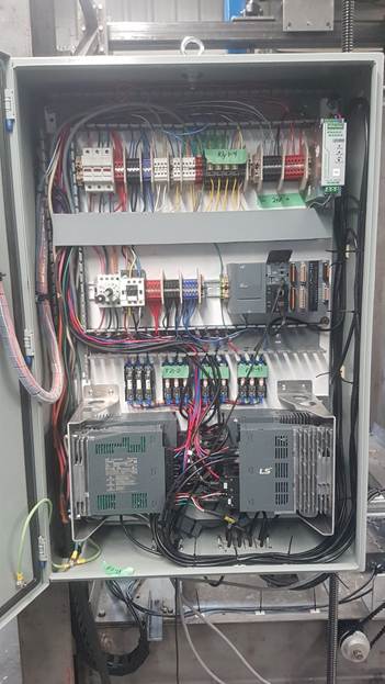
Many small 3D printing systems can get by with economical stepper motors, instead of servo motors. However, this application requires the superior torque and built-in position feedback offered by servos, even though servo systems introduce additional cost and complexity. For their motors and motor drives, the team selected from the range of compatible LS Electric servo motors and drives, ensuring seamless integration with the motion controller.
Each motor was matched with a drive, providing the interface between the motion controller and the motor. Motion control communication used industry-standard EtherCAT, which is a synchronous, high-speed, Ethernet-based protocol, optimized for automation and precise control applications. Implemented with a simple daisy-chain topology using Ethernet patch cords, the team found EtherCAT effective to streamline installation.
Putting Things into Motion
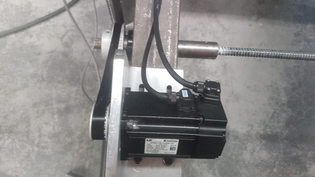
The motors were carefully sized based on torque and rotor/mechanism inertia requirements to drive the mechanisms using pulleys, belts, and ball screws. The team selected two 400 Watt APMC-FBL04AMK-AD motors to control the relatively low-load horizontal axes, while the vertical axis uses a pair of 750 Watt APMC-FCL08AMK-AD motors to handle the much more substantial load (Figure 3).
Since two motors are used in parallel to drive the vertical axis, it was important to implement synchronized motion control using built-in controller features to prevent mechanical binding, with careful error detection and shutdown in the event of any discrepancy. Homing of all three axes is performed by stalling the motors at the end of the machine’s travel range, a process supported both by the motors and motion controller.
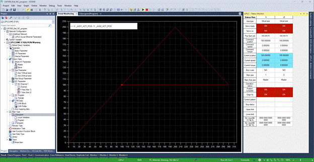
Programming the motion controller was accomplished using the XG5000 software suite, a versatile programming software commonly used with LS Electric programmable logic controller (PLC) and motion controller ecosystem. While the software supports a variety of programming languages, the team chose to use traditional ladder logic for the primary control sequences such as homing the motors and loading the g-code instructions.
Regarding the g-code, the workflow for creating a part is to first develop it as a 3D model using any computer aided design (CAD) tool. This model is then processed through an open-source “slicer” software tool, to render g-code instructions for printing layers. Standard slicers incorporate information relevant for polymer-based 3D printing, so the team needed to scrub this out to preserve just the X/Y/Z motion commands. The resulting g-code is uploaded to the motion controller, which then follows the instructions to perform the manufacturing process.
The final WAAM system design supports a build volume of 3 x 3 x 6 feet, allowing a wide range of maritime parts to be manufactured with ease. With the double-motor driven vertical axis, the machine can support a maximum part weight of 500 kg. It will support the use of several different materials—first mild steel, and later aluminum, brass, and stainless steel.
Building Up to Success
Throughout the project, the team gained valuable real-world experience through exposure to a real-world application and design process, innovative additive manufacturing techniques, and hands-on construction. Using proven, industry-standard automation equipment provided a reliable and straightforward automation experience. The team appreciated the full LS Electric ecosystem, allowing easy motor interconnection, extensibility, programming, and guaranteed compatibility. Using AutomationDirect’s extensive written documentation and video tutorial library, the team was able to navigate the learning curve of using the LS Electric motion controller with ease.
Currently, the team has validated the 3D motion control of the machine by having it perform simple pathing in three dimensions, including attaching a felt-tip marker to it and having it draw pictures on paper.
The next step for the team is to qualify the system by testing the welding mechanism and working towards full-scale manufacturing. Furthermore, the team would like to add automated prediction and compensation for welding factors such as heat stress and material flow, which will further improve the manufacturing quality. These features can be added to the existing motion controller platform, allowing the team to continue iterating and improving their design without significant redesign effort. Looking forward, the project will be continued by other students at SFU and BCIT working on the welding and manufacturing systems, before the machine ultimately finds its home in a shipyard.
All figures courtesy of David Powell.
Author Bio

David Powell served as the automation and control lead on the WAAM project. He is completing a master’s in mechatronics engineering at Simon Fraser University, following on his bachelor’s degree in mechanical engineering.