The Technical Support Team at AutomationDirect receives a large number of calls on RLL Plus (Relay Ladder Logic Plus) programming, also known as “Stage” programming. Most of the callers want to understand how and when it should be used. The short answer to the “when” question is that it depends on the process that is being controlled. The “how” question will be answered later.
Stage is an advanced style of programming that is suitable for a moderately experienced programmer. A thorough knowledge of how the PLC scans the program is necessary to avoid complications. However, it is not a “different” language than RLL. It uses the same instruction set and is scanned in much the same way with a few exceptions.
Stage Programming
RLL Plus or “Stage” programming is well suited to a process that has clearly defined “steps” or stages that will occur multiple times during the process. It is not suited for processes that are linear, and have poorly defined “steps”. For example, making a batch of cookie dough might be a good use for Stage programming, while baking the cookies would not be, since baking only has one step (i.e., cooking the dough.)
A good example to illustrate the use of Stage programming is a machine that mixes bread dough. A bread dough machine has several unique “steps” to create the final product. Some of those steps will be done more than one time throughout the process. As you can see in Figure 1, small portions of the standard RLL program are needed multiple times. For example, the mixer will be turned on and off many times throughout the program. It will always need the same alarms and safeties each time it operates. While you could minimize the amount of ladder by paralleling contacts, it does make a program harder to read. By placing the startup, safety, alarm, and shutdown for the mixer all in one stage, you can enable the same code many times in the program and cut down on your programming time (Figure 2).
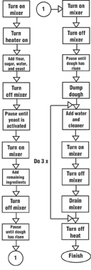
Figure 1
Flowchart example using standard RLL programming
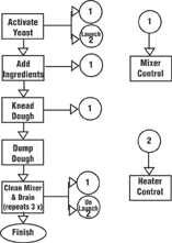
Figure 2
Flowchart example using stage programming
Stages are not like subroutines. They are scanned just as if they are regular ladder logic. The closest thing to a stage is a Master Control Relay. If the MCR is on, then the power rail is processed. If the MCR is off, then the power rail is skipped. Stages operate in much the same fashion. If the stage is enabled, the power rail has power and the logic is executed. If it is disabled, then all logic within that stage is skipped (not processed) because the power rail has no power.
There are three main behaviors to Stage programming:
1) When the stage bit is on, the
corresponding stage is scanned and logic within that stage is evaluated and processed.
2) When the stage bit is transitioning from on to off, the corresponding stage will be scanned one more time to turn off all outputs that are currently on.
3) When the stage bit is off, the
corresponding stage is not scanned and therefore no logic in that stage is
evaluated or processed.
There are some caveats to be aware of with stage programming that concern turning stages on and off. These are detailed in AutomationDirect PLC user manuals, which can be purchased separately or downloaded from www.automationdirect.com.
Stage programming can save PLC memory and improve scan time by reducing the number of repeated sequences and by scanning only the stages that are active. These are two more good reasons to think about using stage programming, but they are not good reasons to use stage if the process is not suited for it.
Stage programming and standard RLL logic style programming can be intermixed by placing standard RLL at the beginning of the program, but usually there is no need to do this. A proper stage program will start with one or more initial stages and have numerous stages that will be turned on and off throughout the program cycle.
There are two ways to activate a stage: with a “Jump” instruction or by setting the stage bit. The Jump instruction deactivates the current stage while activating the specified stage. It does not jump over other code.
Setting the stage bit will activate the specified stage while leaving the current stage running as well. By using Set instructions you can have many stages active at one time.
The Reset instruction works in much the same manner as the Set instruction. You can reset one stage or a whole group of stages at one time using the Reset instruction.
When exiting a stage, whether by jumping out of it or by resetting the stage bit, the stage will always finish scanning before turning the power rail off. When jumping out of the current stage, the current stage will be scanned one more time after the current scan is completed. This behavior can cause problems with some processes if it is not accounted for.
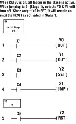
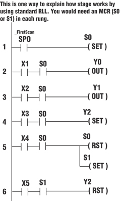
A stage is turned off by jumping out of it or by resetting it. All outputs, timers and counters, unless set, will be turned off. The simple explanation is that turning off a stage turns off the power rail. If there is no power, then the instructions are turned off. Timers and Out instructions, for example, rely on the power rail to maintain their state. Once power is removed, they turn off. This happens with other instructions as well. The following examples show Stage programming and how Stage would look if using Standard RLL:
Stage programming can certainly help organize a program, but it isn’t always useful for every program. The key to help determine if Stage programming should be considered is, “Can this program be broken down into logical steps?” If you can answer “Yes” to that question, then learning Stage programming might help save you some time, both in program development and in execution speed.
by Richard Palmer
AutomationDirect
Originally Published: April 1, 2004