Ahhh… model train displays. There is just something about walking into a showroom with model trains in operation. But what does it take to control the world’s largest indoor train display with over 80?model G-scale trains, more than 1,200 cars, and 50 individual tracks laid down over two miles? Start with a 25,000 square foot facility, and add six AutomationDirect Terminator-based Do-more PLCs with discrete and analog I/O, each one responsible for operating an area of the building. Then network the PLCs together and add programming to allow multiple trains to operate together, some sharing the same tracks and sidings—you now have a complex yet easy-to-operate control system for every model train hobbyist’s dream come true.
Living the Dream
Entertrainment Junction (www.EntertrainmentJunction.com) is the fulfilled dream of owner Don Oeters, a successful Cincinnati businessman and train enthusiast. His vision was to create something unique, a one-of-a-kind family entertainment center that would entertain, educate and promote railroading in a magical environment.
 The attraction would be home to the world’s biggest model train layout and would take visitors on a virtual train journey via an indoor kid’s playground, a railroad museum, a gift shop, and more.
Don’s plan for the museum was simple – make it about the history of railroading, make it interactive, and make it for all ages. The concept drawings were produced by Bruce Robinson, a local architect whose resume includes most of the Ripley’s Believe It or Not museums in the world. Bruce took Don’s concept and created what can only be called an indoor theme park. Response to the drawings was strongly positive and Don decided to move forward with this unusual Cincinnati attraction. Major construction began in early 2007, and work continues to this day as new elements are constantly added.
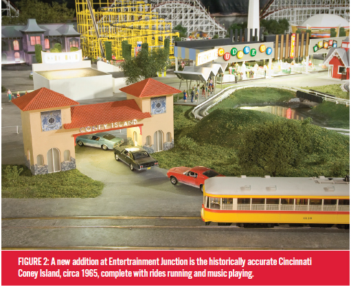
Don continues to push his vision, always adding new structures and train controls to the train display. In June of 2013, phase 2 of the train display was completed on the mezzanine level. The historic Cincinnati Coney Island, circa 1965, was built in G-Scale with rides running and music playing.
Large Scale Simulates Real-World
 Entertrainment Junction uses G-Scale model trains throughout the layout, with the 1:24 scale representing the ratio of the model to real-life size. The G-scale model train is the largest of the mass-produced trains, with 1 inch on the model equating to about 2 feet in real life. These big, burly model trains operate on 2-rail track, use DC power, and can run indoors or outdoors.
Currently, there are over 80 trains operating on 50 individual main lines with electrically-isolated and segregated blocks. This allows for multiple locomotives to be controlled independently within a single track line. In some cases, a single line will have up to seven trains operating at the same time.
The turnouts, railroad switches used to change tracks, are controlled by a small 12 VDC rotary motor that is always either pushing or pulling against the switch via a connecting rod. A relay controls the polarity of the voltage being delivered to the DC motor, therefore controlling the direction of rotation. The continual applied pressure from the connecting rod to the switch allows for secure positioning, eliminating derailments from unsecured rails within the switch.
Upgrading the Control System
Local volunteers and enthusiasts designed and manufactured the original control system by hand. The custom printed circuit boards with resistors, diodes, transistors, capacitors and other electronic components were all soldered and assembled on site. Each track had its own control panel containing all the parts and pieces that make up the control system. 45 control panels were originally made, and more were eventually added to accommodate the growing business.
A single computer ran the original circa 1970s C programming language, written before C++ was even developed, and power to the trains was regulated in an analog fashion via a single capacitor and several transistors.
After running well for six years, maintenance on the original control system became very problematic. When something wore out, broke or failed, it had to be repaired by hand. Replacement parts were not available for much of the hardware or components.
A more flexible control system was needed for this large distributed control application, and AutomationDirect was selected as the primary supplier. I chose AutomationDirect because of my favorable experiences with the company in the past. Several reasons include the abundant supply of equipment to choose from, fast delivery and great customer support. It really is a pleasure knowing that you can get what you need quickly, with any support you may need just a phone call away.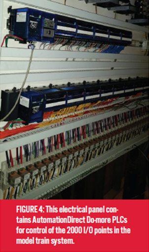
The new control system is a 100% retrofit, completely replacing the older control hardware with AutomationDirect components. Up to eight AutomationDirect Do-more PLCs are planned, each one using 55 discrete 16-point input modules, 40 discrete 16-point output modules, and 30 analog 16-point 0-10 VDC input and output modules.
The control system simultaneously monitors over 850 magnetic reed sensors and control buttons, over 640 12VDC relays and indicator lamps, and over 500 individually controlled blocks. It also provides voltage control for the engines. Other control functionality includes bridge up/down, traffic signals, switches, speed changes, stops and starts.
The new control system is responsible for controlling multiple trains on multiple tracks simultaneously. In most cases, multiple trains are operating together on the same tracks, with state logic programming coordinating the locations and speeds of each train. The old system had a single control panel for each train, operating independently from the rest of the layout. The new configuration ties every train and track together into one main control system, which allows for much more diversity on how the trains can operate, both individually and in relation to each other.
The old system controlled the voltage feeding the track using a combination of NPN transistors, optical amplifiers, resistors and capacitors. The acceleration and deceleration for the locomotives was provided by adjusting analog potentiometers on the control board, thereby increasing and decreasing resistance in the circuit.
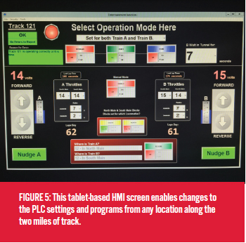
With the new control system, all analog voltages are controlled by the PLCs. Each PLC has a built-in web server, allowing speed control voltages and other values to be set using a web thin client running on an iPad or Surface tablet. Acceleration and deceleration rates can also be adjusted, along with many other parameters. The web client also provides a comprehensive view of train operation, along with the ability to drill down to more detailed levels as required by the operator.
Several of the tracks in the layout have grade changes, requiring the trains to travel both uphill and downhill within a single lap. With the old system, only one voltage level could be set for the whole lap. The new system is always monitoring the resistance load on the locomotive, and will increase or decrease the supplied voltage automatically based on if the train is travelling uphill or downhill. This allows the trains to operate at a constant speed.
Keeping an Eye on the Train Schedule
While running over 110 trains, there is a high demand for retrieving information. For data acquisition, the PLCs count laps for each train and record fastest lap time, slowest lap time, average lap time, voltage input versus voltage output (allows for resistance detection), and the locations of the trains.
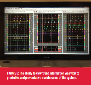
By using trend views inside the Do-more programming software, voltage spikes and dips can be detected. This vital information lets the staff know when a track needs to be cleaned, or if a train is drawing more amps than it should. Voltage spikes on a graph indicate points along the track where the locomotive briefly lost continuity with the rail, indicating dirty track or wheels. On the other hand, voltage dips indicate heavy resistive loads, perhaps due to a stock car’s wheels shorting out while in motion, or bad motor brushes on a locomotive engine.
The PLC is programmed to automatically recognize these issues and alert Entertrainment staff via email if a track needs cleaning or if there are any issues with rolling stock. In extreme cases, the PLC will automatically shut down an operating line if a voltage dip exceeds a threshold over a set period of time, for example, dead shorts lasting longer than 0.5 seconds.
Controlling a Speeding Train
Analog signals are used to control the voltages supplied to the rails on the tracks, which then power the locomotives. It’s imperative that trains accelerate and decelerate at certain rates so damage does not occur to the locomotives. The PLC’s analog voltage output modules are rated 0-10 VDC on all systems. The train’s operating voltage is between 0 VDC and 24 VDC, with an average amp load of anywhere from 2 amps to around 5 amps.
Since the analog output modules are not designed to handle this high of load, a custom amplifier board was designed, converting the low-level 0 to 10 VDC output to an amplified, high-current 0 to 24 VDC output. This amplified voltage then feeds a 40 amp power transistor that drives the power to the locomotives. The power transistor is doing the work of supplying the current to the locomotive, with the PLC simply providing a control voltage which regulates the transistor’s output.
The PLCs monitor the track’s segment block voltage by converting the 0 to 24 VDC operating voltage to 0 to 10 VDC using four meg-ohm resistors. Using a math function in the PLC, the scaled 0 to 24 VDC railroad track voltage is monitored. With Ohms law and the fact that a DC motor running with a steady load will look resistive to a steady-state DC supply, train engine operation can be effectively monitored. The resistance of the locomotive can also be determined, providing a solid representation of the power draw on the track.
This power draw information gives an indication of where there are continuity issues such as a dirty track. A lower voltage return indicates a higher resistive load. A threshold is set within the control system, and any reading higher or lower than the threshold will cause the train to shut down and send a text message to an operator’s phone for immediate investigation.
The control system monitors the voltages continuously to catch overload issues, often before the circuit breaker trips. Rolling stock cars have axles that often wear and cause shorts, and inputs to the PLC’s analog modules detect when that behavior is present and stops the train.
The supervisory control and data acquisition (SCADA) system was launched with the help of Steve Caar and Larry Koehl, volunteers from Greater Cincinnati Garden Railway Society. They helped transfer all the variables and resources needed from the old system to the new one. The new SCADA system consists of AutomationDirect’s Point of View PC-based operator interface software with four web thin clients. Each thin client provides mobile access on Apple iPads or Microsoft Surface Pros. The SCADA system had just as much if not more programming time involved than the PLC programming, as it provides a comprehensive operator interface to the entire train system.
PEERLINK for Ethernet was used as the communication network, allowing all the PLCs to talk to each other, either directly or through the SCADA system. The PEERLINK instruction makes it simple to share data over Ethernet between multiple Do-more CPUs, with transparent data sharing using peer logic variables in a designated memory area.
Train Program on Schedule
During the design stage, a test track was set up in a remote location and several months were spent coming up with solid, tested PLC programs.
State logic programming is the primary backbone for all the programs in this model train system. On the tracks themselves, there are magnetic sensors located throughout the entire track line, and some tracks may have up to 36 sensors. A rare earth magnet is mounted on both the front and the rear of each train to activate these sensors. Each time a magnet sensor is hit, the state of that particular train is changed.
From there, the programming possibilities are almost endless. For example, the system can detect if a train is broken in two simply based on if a magnet sensor is activated while the train is under a given state assignment.
If a train hits a sensor under incorrect state parameters, the system will shut down that train, preventing operating malfunctions or potential train collisions. A message will then be sent to the SCADA system describing the error and the location of the train. Usually within seconds, the problem is identified and a plan is established to correct the mishap.
All Aboard
AutomationDirect was very helpful in providing troubleshooting techniques in the research and design phase of the project. Many people were involved in making this retrofit successful, both at our facility and at AutomationDirect, and results have exceeded all expectations.
Troubleshooting a train problem now takes minutes instead of hours. Receiving email alerts when there is a problem, rather than waiting for a guest to tell us, is also very helpful.
The new control system will pay for itself in just three years, and this doesn’t take into account the improved operation, just the maintenance and repair savings. With the added motion sensors, run time on the trains is less than half what the old system was, more than doubling the life expectancy of the locomotives.
The most challenging aspect of the whole project was transitioning to the new control system one track at a time, so that only one or two trains were down during a given day. At the end of the line, with AutomationDirect and all the people who helped us at the facility, the train arrived at the station on time.
By Brian Kienlen,
Fluid Power and Mechanical Products
Master Electronic Operations Director at Entertrainment Junction
 Brian Kienlen has over 14 years of experience working with PLCs operating animation and coasters. Kienlen studied Aviation Technical Engineering at Bowling Green State University in Ohio. In addition to Entertrainment Junction, he works with the Kings Island amusement park equipment and animation, and at Rozzi’s Fireworks for their pyrotechnic displays at Cincinnati Reds games.