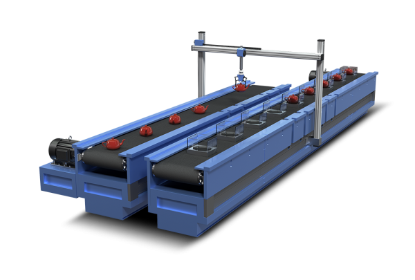
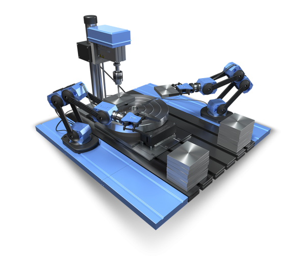
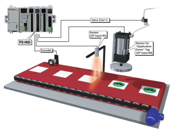
Motion control is generally understood to mean the use of servo and/or stepper systems as the “muscle” to move a given load. These motion control systems are capable of extremely precise speed, position, and torque control. Applications which require positioning of product, synchronization of separate elements, or rapid start/stop motion are all perfect candidates for the use of motion control. PLCs are very capable of providing the signals required to command these servo and stepper systems in a cost-effective and digital (noise-free) manner.
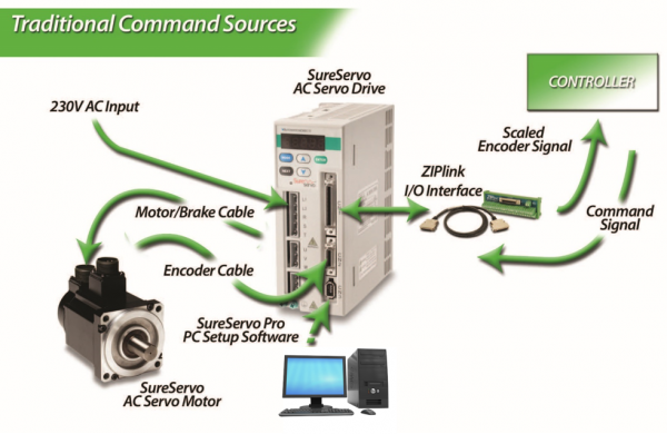
In a typical motion control system there are three basic components: the controller, the drive (sometimes referred to as an amplifier), and the motor. The path planning or trajectory calculations are performed in the controller, which sends low-voltage command signals to the drive, which in turn applies the necessary voltage and current to the motor, resulting in the desired motion. Sometimes feedback devices on the motor or the load are used to notify the drive or the controller with specific details about the actual movement of the motor shaft or the load. This feedback data is used to increase the accuracy of the motion, and can be used to compensate for dynamic changes that may occur at the load, such as changes in mass, friction or other disturbances. Servo systems operate in a closed-loop fashion and vary output torque to move into/stay at the commanded position, while most stepper systems typically provide open-loop position control (a stepper will drive at full force to get to the commanded position or fail trying).
The choice of open-loop versus closed-loop control depends on many factors and both are useful methods for controlling motion. PLC-based controllers can be used for either type of system. Applications that can be accomplished with a low-cost PLC and servo/stepper components include cut-to-length, indexing tables or conveyors, and x/y tables (plotter/cutter/router/placer).
The classic ‘pulse and direction’ signals that are widely used with PLCs provide an inexpensive, noise-free (digital) method for precision motion control. Extensions or function blocks within the PLC ladder logic are typically used for programming and are easy for factory personnel to understand and maintain. While typically limited to a few axes of control and where coordination between axes is limited, PLC controllers with pulse and direction capability are an excellent fit for many motion applications. Often, low-cost PLCs are already being used for logic control on the machinery and can also handle the motion tasks with the addition of a pulse output card and some additional programming. This can eliminate the need to integrate the logic controller with a separate motion controller. Machine builders can also save considerable time when implementing PLC-based systems, especially if they are already familiar with the PLC and its programming software.
In a typical PLC-based motion control system, high-speed pulse output cards are used in the PLC to generate a ‘pulse train’ for each servo or stepper drive. The drive receives the pulses and indexes the motor shaft by a pre-set amount for each pulse. Typical stepper systems might index 1/200 of a revolution per pulse, while micro-stepping or servo systems might be configured for as little as 1/10,000 of a revolution for each incoming pulse. The amount of motion dictated by a single pulse can be adjusted in the drive to obtain a desired resolution, or to achieve a required top speed (as a resolution/top speed trade-off may be required to accommodate the maximum pulse output frequency from some PLCs). A separate signal is used to determine the direction of travel. This control method is referred to as ‘step and direction’. A similar but functionally equivalent method, ‘clockwise/counterclockwise’, uses a separate pulse train for each direction of travel. This method is somewhat less popular, but has advantages in some applications. Electronic gearing can usually be enabled in the drive to allow high-resolution moves at low speeds, as well as a high-speed mode for faster moves with lower resolution.
Encoder feedback, when used in these types of systems, is normally handled at the drive level. Two simple hardwired signals from the drive back to the PLC, drive fault and in-position, are often used to notify the PLC of exceptions and/or completion of each move.
Evolution of Electric Motion Control Technology
Electric motion control systems originated as alternatives to hydraulic motion systems. With most electric systems ranging in size from a few watts into the kilowatt range, electric motion control has become prevalent at these smaller sizes, while hydraulic systems continue to dominate the larger applications approximately 5kW and above, where electric power is impractical or unavailable and where the environment is harsh or extreme. The electric systems are more factory-friendly, less obtrusive, and are easier to install than the plumbing required by hydraulics. Early electric servo systems were usually operated in velocity or torque mode, accepted analog command signals, and were quite successful despite problems with electrical noise and drift. Early PLC-based controllers used analog output cards to provide the velocity or torque command signals.
While analog control signals are still used on some systems, most modern motion systems have migrated to some form of digital control. The advent of the digital servo drive, with the ability to close the position loop, was another major step forward. New types of signals between the controller and drive are now required to send position commands to these digital servo drives.
The three most common control signals used by today’s PLC-based motion controllers are the pulse and direction signals detailed earlier, discrete signals to an intelligent or indexing drive, and fieldbus communications.
The pulse and direction interface that was originally developed for stepper systems has now become a standard feature on most servo products as well. A PLC with a high-speed output is one of the most cost-effective methods for controlling motion today. No intelligence is required in the drive and all programming is performed in the PLC. Almost all PLCs available from AutomationDirect offer some form of high-speed pulse output. For example, the smallest and least expensive DirectLOGIC® PLC, the DL05, includes a single 7kHz high-speed output which can be used for limited motion control applications. The DL05 will also accept an optional module which provides an additional high-speed output channel at up to 250kHz. The AutomationDirect SureStep stepping system can easily be controlled by this or newer PLCs such as the Productivity2000. In addition to the benefit of the low price for stepper components, all motion and logic instructions are programmed in the PLC’s software for significant time savings.
Indexing drives offer another two options for PLC-based control. Indexing drives include a standalone controller which is built in to the servo or stepper drive. These single-axis devices have I/O capability, and can execute motion profiles based on a single PLC or real world input. This type of drive often includes a fieldbus connection and can perform moves based on commands and parameters received across such a connection.
For example, the SureServo® line of servo products from AutomationDirect are indexing drives. The SureServo drives can be pre-programmed with parameters for up to 8 separate motion profiles, which can then be initiated via discrete inputs from a PLC or signals from other devices, even pushbuttons. These moves can consist of precise, user defined accelerations (ramps) to preset speeds, with accurate decelerations carefully timed to end at predefined positions. Dynamic velocities (with controlled ramps) and precise application of torque are also possible. Parameters for vibration suppression (notch filters), load inertia range, proportional and integral gain, and many others can also be customized for specific applications in the SureServo drive. The SureServo offers two adaptive auto-tuning modes, which continue to tune the system while it operates.
The AutomationDirect SureStep® line of stepper products also includes drive models with built-in indexers that offer similar capabilities.
The SureServo products also have a built-in Modbus interface. Modbus-enabled PLCs can initiate moves and download parameters to the SureServo drive across the Modbus link. The Modbus link can also supply information back to the controller about the performance and status of the servo motor and drive system. Multiple SureServo systems can be controlled via a single Modbus port on the PLC. The SureServo’s ability to download custom motion profiles from a PLC on the fly, and execute these moves on command, allows the ultimate in flexibility and control with a PLC-based motion controller.
Trends in PLC-based Motion Control
Motion control modules for PLCs are increasing their capabilities year after year. High-speed output modules offered by AutomationDirect now have output frequencies up to 1 MHz. The Productivity2000™ high speed output module provides two 1MHz output channels that can allow extremely high resolution settings in the drives while also commanding very high (if not “top”) motor speeds when required. These new high-speed output cards are designed to be low-cost “mini-coprocessors”, capable of executing logic asynchronous to the PLC scan.
Software is also playing a bigger role in the evolution of PLC specialty modules for both discrete and hybrid control applications. Advancements in software that provide for intuitive graphical configuration are eliminating the need for large amounts of setup ladder logic previously needed in the beginning of the user’s PLC program. Microsoft Windows-based point-and-click configuration utilities are becoming more common and provide substantial time savings for programmers and maintenance personnel. With these advancements in PLC technology, PLCs will continue to meet the needs of machine control applications for many years.


