Motion control is generally understood to mean the use of servo and/or stepper systems as the “muscle” to move a given load. These motion control systems are capable of extremely precise speed, position, and torque control. Applications which require positioning of product, synchronization of separate elements, or rapid start/stop motion are all perfect candidates for the use of motion control. PLCs are very capable of providing the signals required to command these servo and stepper systems in a cost-effective and digital (noise-free) manor.
In a typical motion control system there are three basic components: the controller, the drive (sometimes referred to as an amplifier), and the motor. The path planning or trajectory calculations are performed in the controller, which sends low-voltage command signals to the drive, which in turn applies the necessary voltage and current to the motor, resulting in the desired motion. Sometimes feedback devices on the motor or the load are used to notify the drive or the controller with specific details about the actual movement of the motor shaft or the load. This feedback data is used to increase the accuracy of the motion, and can be used to compensate for dynamic changes that may occur at the load, such as changes in mass, friction, or other disturbances. Servo systems operate in a closed-loop fashion while most stepper systems provide open-loop control of position. The choice of open-loop versus closed-loop control depends on many factors and both are useful methods for controlling motion. PLC-based controllers can be used for either type of system.\
Types of Industrial Motion Controllers
Historically, there have been three basic types of controllers used for motion systems; standalone controllers, PC-based controllers, and PLCs.
Standalone motion controllers are usually dedicated devices or option cards that are purpose-built for motion applications. They are typically very good at controlling motion, but most are expensive, sometimes difficult to integrate into the overall machine control system, and may use analog or proprietary signals for communication with the drives. Programming languages are often proprietary and may require high-level engineering assistance for basic troubleshooting and programming changes. Standalone controllers are usually sold based on an axis count with 2, 4, 8 and even 16 axes of control being common. Tight coordination between multiple axes of motion is possible with these controllers.
PC-based motion controllers are a more recent option. These controllers have evolved from the standalone controllers, and have both advantages and disadvantages. PC-based controllers can handle high axis count applications with requirements for tight coordination between axes and usually benefit from the extensive communication options available on a PC platform. PC-based motion can also be integrated with PC-based logic control and HMI software, often running on the same hardware platform for integrated “single box” control for a machine. But PC-based motion is also expensive and suffers from ease-of-use and maintenance issues, with motion control code often written in proprietary or complex programming languages. Some PC-based controllers are nothing more than standalone controllers that happen to fit inside the PC. These motion control “cards” use the PC bus for communication and power, but they are still proprietary controllers with motion specific circuitry, which do not utilize the processing power of the PC.
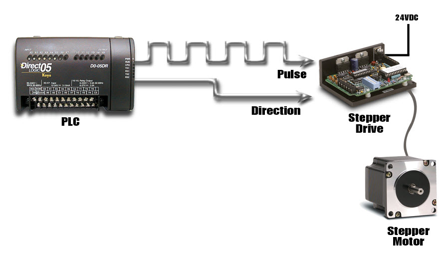
The third type, PLC-based control, is often considered to be the simplest way to control motion. The classic ‘pulse and direction’ signals that are widely used with PLCs provide an inexpensive, noise-free (digital) method for precision motion control. Extensions or function blocks within the PLC ladder logic are typically used for programming and are easy for factory personnel to understand and maintain. While typically limited to a few axes of control and where coordination between axes is limited, PLC controllers with pulse and direction capability are an excellent fit for many motion applications. Often, low-cost PLCs are already being used for logic control on the machinery and can also handle the motion tasks with the addition of a pulse output card and some additional programming. This can eliminate the need to integrate the logic controller with a separate motion controller. Machine builders can also save considerable time when implementing PLC-based systems, especially if they are already familiar with the PLC and its programming software.
In a typical PLC-based motion control system, high-speed pulse output cards are used in the PLC to generate a ‘pulse train’ for each servo or stepper drive. The drive receives the pulses and indexes the motor shaft by a pre-set amount for each pulse. Typical stepper systems might index 1/200 of a revolution per pulse, while micro-stepping or servo systems might be configured for as little as 1/10,000 of a revolution for each incoming pulse. The amount of motion dictated by a single pulse can be adjusted in the drive to accommodate the maximum pulse output frequency from the PLC. A separate signal is used to determine the direction of travel. A similar but functionally equivalent method, clockwise/counterclockwise, uses a separate pulse train for each direction of travel. This method is somewhat less popular, but has advantages in some applications. Electronic gearing can usually be enabled in the drive to allow high-resolution moves at low speeds, as well as a high speed mode for faster moves with lower resolution.
Encoder feedback, when used, is normally handled at the drive level. Two simple hardwired signals from the drive back to the PLC, drive fault and in-position, are often used to notify the PLC of exceptions and/or completion of each move.
Early Methods Of Motion Control
Electric motion control systems originated as alternatives to hydraulic motion systems. With most electric systems ranging in size from a few watts into the kilowatt range, electric motion control has become prevalent at these smaller sizes, while hydraulic systems continue to dominate the larger applications approximately 5 kW and above, where electric power is impractical or unavailable and where the environment is harsh or extreme. The electric systems are more factory-friendly, less obtrusive, and are easier to install than the plumbing required by hydraulics. Early electric servo systems were usually operated in velocity or torque mode, accepted analog command signals, and were quite successful despite problems with electrical noise and drift. Early PLC-based controllers used analog output cards to provide the velocity or torque command signals.
Motion control systems have allowed machine builders to move away from line shaft driven machines, where all motion was geared back to a single large motor or line shaft. Gears, chains, cams, and pushrods were employed to create all of the desired motions at each point on the machine. While these machines were functional, they weren’t very flexible, and often required changing parts for different sizes and types of products. Spare gears with different numbers of teeth and various mechanical cams with different shapes were required to perform a change-over for different sizes of product or machine configurations. The time required to complete the change-over was also an issue, with lengthy downtime required for maintenance personnel to complete the changes. Once the mechanical change-over was completed, the machines could require a lengthy adjustment period until the new set-up was optimized.
More Recent Motion Control Technology Enables
The concept of software-based change-over. With each motion on a machine controlled by a separate motor, new motion control parameters can be quickly implemented, converting the machine to a saved configuration without having to replace mechanical components.
Modern Motion Control Technology
One beneficial technology for modern motion control is the permanent-magnet brushless motor. The old brush-type motors were less efficient, and required brush replacements at regular intervals. Advancements in magnet technology have enabled the design of compact, powerful motors, whose rotors require no electrical connections (or brushes). Virtually all modern motion control systems, both servo and stepper-based, now employ brushless motor technology.
 While analog control signals are still used on some systems, most modern motion systems have migrated to some form of digital control. The advent of the digital servo drive, with the ability to close the position loop, was another major step forward. New types of signals between the controller and drive are now required to send position commands to these digital servo drives.
The three most common control signals used by today’s PLC-based motion controllers are the pulse and direction signals detailed earlier, discrete signals to an intelligent or indexing drive, and fieldbus communications.
The pulse and direction interface that was originally developed for stepper systems has now become a standard feature on most servo products as well. A PLC with a high-speed output is unquestionably the most cost effective method for controlling motion today. No intelligence is required in the drive and all programming is performed in the PLC. All of the PLCs available from AutomationDirect offer some form of high-speed pulse output. Even the DL05, AutomationDirect’s $99 PLC, includes a single 7kHz high-speed output which can be used for limited motion control applications. The DL05 will also accept an optional H0-CTRIO module which provides an additional high-speed output channel at up to 25kHz. The AutomationDirect SureStep stepping motor, drive, and required DC power supply start at $267 for a single axis of motion, and can easily be controlled by the DL05. In addition to the benefit of a low price, all motion and logic instructions are programmed in the DirectSOFT programming software for significant time savings.
Indexing drives offer another two options for PLC-based control. Indexing drives are a combination of a standalone controller built in to the servo or stepper drive. These single-axis devices have I/O capability, and can execute motion profiles based on a single PLC or real world input. This type of drive often includes a fieldbus connection and can perform moves based on commands and parameters received across such a connection.
The new SureServo line of servo products from AutomationDirect (available summer 2005) are indexing drives. The SureServo drives can be pre-programmed with parameters for up to 8 separate motion profiles, which can then be initiated via discrete inputs from a PLC or signals from other devices, even pushbuttons. These moves can consist of precise, user defined accelerations (ramps) to preset speeds, with accurate decelerations carefully timed to end at predefined positions. Dynamic velocities (with controlled ramps) and precise application of torque are also possible. Parameters for vibration suppression (notch filters), load inertia range, proportional and integral gain, and many others can also be customized for specific applications in the SureServo drive. The SureServo offers two adaptive auto-tuning modes, which continue to tune the system while it operates.
The SureServo products also have a built-in MODBUS interface. MODBUS enabled controllers, including PLCs, can initiate moves and download parameters to the SureServo drive across the MODBUS link. The MODBUS link can also supply information back to the controller about the performance and status of the servo motor and drive system. Multiple SureServo systems can be controlled via a single MODBUS port on the PLC. The SureServo’s ability to download custom motion profiles from a PLC on the fly, and execute these moves on command, allows the ultimate in flexibility and control with a PLC based motion controller.
The Future of PLC-Based Motion Control
While it is difficult to predict the future, AutomationDirect is always interested in the enhancements and features that our customers are requesting. Features that are frequently requested are higher speed output cards for our PLCs, easier to use configuration software, and high level function blocks in the ladder programming environment.
The current high-speed CTRIO modules offered by AutomationDirect have a maximum output frequency of 25kHz. While this is sufficient to command motion at high speed (4500 RPM at roughly 330 pulses per revolution), or high resolution (8000 pulses per revolution, up to 375 RPM), users are asking for outputs that would allow both high speed and high resolution without any trade-off.
Software is playing a bigger role in the evolution of PLC specialty modules for both discrete and hybrid control applications. Advancements in small footprint microprocessors and the acceptance of flash ROM memory, combined with software that provides intuitive graphical configuration, are eliminating the need for large amounts of setup ladder logic often needed in the beginning of the PLC user program. These new breeds of specialty modules, such as high-speed output cards or motion control modules, are being designed as low-cost “mini-
coprocessors”, capable of executing logic asynchronous to the PLC scan. Microsoft Windows-based point-and-click configuration utilities are becoming more common and provide substantial time savings for programmers and maintenance personnel. With these advancements in PLC technology, PLCs will continue to meet the needs of machine control applications. They will stay more cost-effective and easier to use than PC technology, or separate logic and motion platforms, and will do so in a much smaller package.
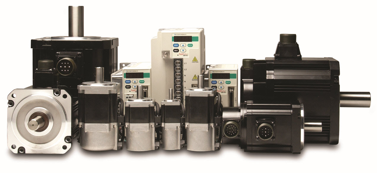
SureServo™ Servo Systems Coming Soon
Available in summer of 2005, the SureServo AC servo systems range in size from 100W to 3kW continuous power and provide from .08 to 26.4 ft·lbs of peak torque. They can be powered with single or three phase 230 VAC. The SureServo drives can be controlled in position, velocity or torque mode. All SureServo motor sizes will be available with or without a 24 VDC holding brake.
![]()
Precise Positioning
SureServo systems are easily controlled via ‘step & direction’ or ‘step-up/step-down’ commands from any PLC with a high-speed output. Electronic gearing can be used to scale the incoming pulse frequency from the PLC. This allows the pulses from the PLC to command the exact amount of movement required for a specific application.
The SureServo drive’s on-board indexer will allow the programming of up to eight unique motion profiles. Discrete inputs can be used to initiate any of these profiles. The built-in MODBUS interface will offer the flexibility of downloading customized motion profiles to the drive as they are needed. These profiles can be selected and executed based on additional MODBUS commands or via discrete inputs.
Complete Control
Eight programmable inputs and five programmable outputs assure real-time connectivity with any control system. Velocity and torque can be controlled with a ±10V analog input signal or with the onboard indexer. One analog output will be available and configurable for monitoring purposes.
Tune-up and Tune-in
Three tuning modes include: manual, adaptive easy-tune, and adaptive auto-tune. The adaptive modes allow the drive to adapt to dynamic load conditions during operation with little or no initial set-up required.
The SureServo drive parameters can be changed from the drive’s built-in keypad or the PC set-up software. SureServo drives will communicate via a MODBUS interface across RS-232, 422, or 485 serial links. AutomationDirect will offer standard cable sets from 10 to 100 feet in length.
System prices will start around $700 for a 100W motor, drive and 10 foot cables.
By Chip McDaniel
AutomationDirect
Originally Published: March 1, 2005