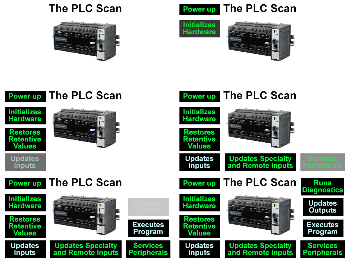
With PLC control, it’s important to understand the sequence of operations for the CPU. Some may think when an output is set to ON in the ladder code, that this output change is immediately reflected in the output card. Or that when an input is activated, the CPU instantly sees it. While it may seem that way to the naked eye, that is not actually the case. The output and the input will only be updated once the PLC scan gets to the appropriate step in the sequence. To us, that seems immediate, but to a computer it may not be. With inputs, the time it takes the CPU to notice a change can vary depending on where the CPU was in the sequence when the input turned on. The amount of time the CPU needs to complete one scan is known as scan time and it can adversely affect your process if you are not careful.
The PLC Scan Sequence
As a programmer, you’re mostly concerned with three main steps in the PLC scan – the Update Inputs, Execute Program and Update Outputs steps. But there are other steps that need to be considered as well. Most PLCs will have similar sequences, some with a few variations, and the sequence is as follows:

- Power Up – this is the starting point when the PLC is first powered
- Initialize Hardware – at this point, the CPU will verify and initialize the installed hardware
- Restores Retentive Values – any CPU memory locations that were configured as retentive will be restored to their previous value
- Updates Inputs – the CPU will now read in the inputs stored in the input table, on the next scan this will be the starting point for the CPU
- Updates Specialty and Remote Inputs – the CPU will take in any inputs from specialty modules, like high-speed counters, and remote I/O racks
- Service Peripherals – in this step, the CPU will handle any requests from the serial or Ethernet communication ports
- Executes Program – if in the RUN mode, the CPU will now execute the ladder program using the updated inputs
- Updates Outputs – If there were any output state changes from the ladder execution, the CPU will now right them to the output tables and in turn the output cards
- Diagnostics/Housekeeping – finally the CPU will run a self-check and tie up any loose ends before repeating the scan – returning to the “Update Inputs” step
What To Watch For
Modern PLCs can run the scan in milli-seconds and for most applications that is not a problem. But as your code complexity increases, the time it takes to execute can begin to slow the CPU. This can be greatly alleviated by using program efficiencies like subroutines and task management. Another thing to watch for in regard to CPU scan time is the amount of communication requests coming into the CPU. If the application is communication heavy and there is a lot of polling of information frequently, the CPU scan can be adversely affected.
PLC scan time can be a big issue with high-speed applications. Let’s say you are controlling a high-speed sorting facility, and for packaging tracking purposes your encoders are supplying 1000 pulses per revolution for every foot of a 140-fpm conveyor.

That is over 2,000 pulsed signals per second or over 2 pulses every milli-second. At that rate, the average CPU is bound to miss a few and in turn could cause a diverter arm to miss or crush a box. In these situations, specialty modules like high-speed counters, can be used to ensure no pulses are missed. These counters are designed to work independently from the CPU scan, meaning they have their own processor dedicated to tracking the pulses coming in and nothing else. They then feed the count over to the CPU when it is requested.
For more information on PLC scan time and many other PLC topics, visit our FREE Online PLC Training Portal to take advantage of Interconnecting Automation’s online PLC video training series.
To read more articles about programmable control, click here.
Originally Published: February 2019


