By: Joshua Draa and Larry Reynolds, Automation Direct
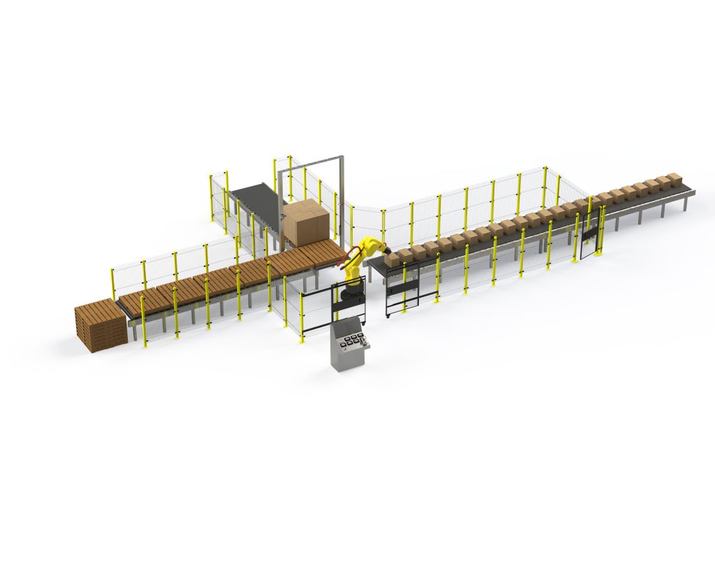
Safety is an essential aspect of machine design and operation, protecting personnel, guarding against equipment damage, and maximizing productivity. The purpose of a safety system is to bring a machine to a known safe state as quickly as possible after a safety sensor detects a hazardous condition or a member of staff presses the emergency stop.
At its most basic, a safety system consists of:
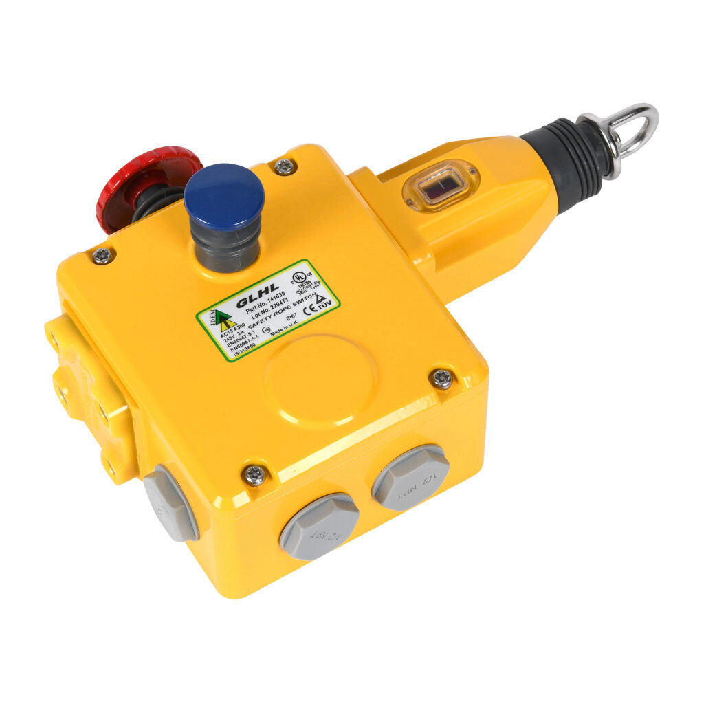
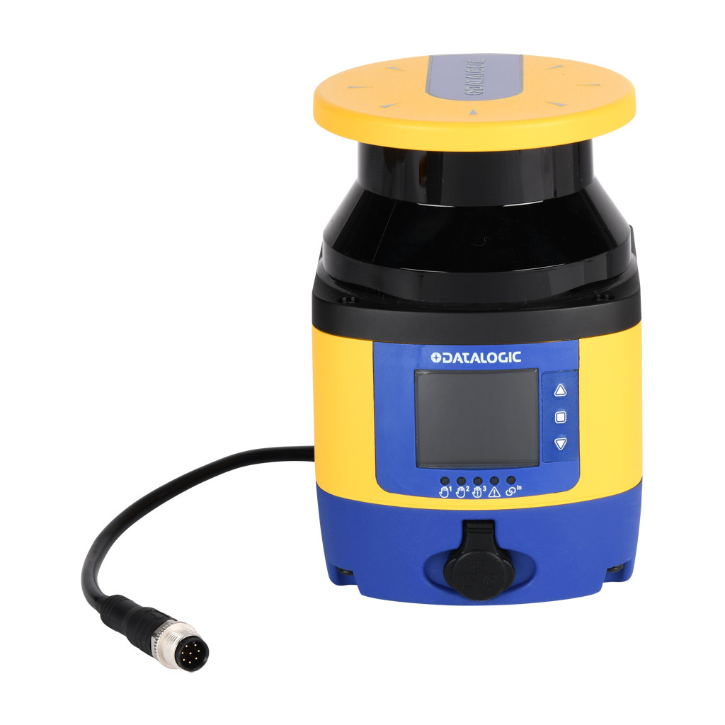
- Input – sensors that detect hazardous conditions, such as personnel entering restricted zones (e.g., safety switches, light curtains, mats, edges, etc., as well as E-stop buttons or cable pulls)
- Logic – devices that monitor safety input and control safety outputs (e.g., safety relays, safety PLCs, etc.)
- Output – devices to bring the machine to a known safe state by controlling hazardous motion (e.g., safety contactors, variable-frequency drives (VFDs) with safe torque off, etc.)
A wide variety of machine safety technologies exists, from simple barriers to highly sophisticated zone safety implementations. More expensive or complex isn’t necessarily better, however. The ideal safety system is one that addresses the needs of the machine and the application to ensure safety without adding unnecessary complexity and cost. Here, we review our top tips for building a safe system.
Tip #1: Start with a Risk Assessment
Safety should not be considered a separate subsystem layered on top of the machine design as an afterthought. Instead, it should be integrated from the very beginning of design, starting with a risk assessment.
The key steps to a risk assessment are:
- Assembling a cross disciplinary team – design/engineering, equipment function, operations, maintenance, etc. This ensures that no one silo can dominate the conversation.
- Identifying risks, the frequency/duration of worker exposure to those risks, and the possible negative outcomes. Operators are not the only individuals to consider. The risk assessment should take into account any interaction with the machine, whether for cleaning, maintenance, monitoring, or simply passing by.
The primary standards for safety design and risk assessment include ANSI B11.0, ANSI B11:19, and ANSI/RIA R15.06, or ISO 12100, and ISO 13849. Don’t forget to consider application-specific standards and location-specific requirements.
Tip #2: Reduce Risk Through a Multilayered Safety Approach
Once you identify risks, create a strategy for reducing them. Start by eliminating hazards where possible. If this can’t be done, try to modify the design to reduce the level of risk. If a moving part needs to be inspected regularly but accessed only infrequently, for example, change from a door to a transparent window that can only be removed with tools. Note that risk elimination/substitution is easier and less disruptive when performed at the start of a design. This is another benefit of performing risk assessment and mitigation at the start of design.
If a risk can’t be eliminated or substituted, reduce risk using a combination of safety solutions. Safety light curtains, for example, are useful for detecting when personnel have moved into a restricted area, but they can’t protect them from objects flying out of the machine. A safety door can prevent objects from exiting the machine, but it needs a sensor to invoke it. A safety mat can detect personnel in an unsafe position. A safety controller can put the machine in a known safe state by sending the command to close the safety door, but what if an operator’s hand is in the way? A safety edge can detect a pinch hazard and provide the sensory input into the system to safely stop the motion.
This is the type of layered safety system that a risk assessment makes possible.
Tip #3: Don’t Assume Removing Energy Sources Guarantees a Known Safe State
A common technique for reducing risk presented by a moving actuator, motor, or similar device is to remove energy from it. Although this is a useful technique, it’s not necessarily sufficient to achieve our goal of driving the system to a known safe state. A de-energized motor freewheeling to a stop can still present a hazard – active braking may be necessary. Removing compressed air from a pneumatic cylinder could cause an elevated load or tooling to fall, potentially injuring personnel or damaging equipment. Certain types of equipment require more sophisticated approaches.
IEC 60204-1 or NFPA 70 define three stop categories they can be used to better manage risk:
- Category 0: An uncontrolled stop initiated by immediately removing power to the device
- Category 1: A controlled stop accomplished by active braking using available power, then removing power once the device is at rest.
- Category 2: A controlled stop, after which the actuator remains energized but stationary.
Bringing a moving piece of equipment to a safe state may require a Category 1 or Category 2 stop.
During the mitigation process, be sure to perform the crucial step of comparing your mitigation plan to the risk assessment, and ask yourself these questions: Is the risk level now at an acceptable level, and did we create a new hazard by mitigating the previous hazard?
Tip #4: Safety Doesn’t Have to be Complicated or Expensive
It’s an engineering truism that there is no one perfect solution, only the best choice for the project at hand. In the risk reduction phase of your risk assessment, consider the simplest, most robust solution that will ensure the level of protection required.
Your safety system can be as simple as a non-contact door switch, wired in series with an E-stop to a safety relay that controls a safety contactor. Or, you can use a zone safety approach, in which specific safety devices are assigned to one or more zones, with each output device functioning as an independent zone. Zone safety improves both risk reduction and productivity with a more granular application of safety principles. The trade-off is cost and complexity.
Tip #5: Choose a Solution Designed to Resist Defeat
For as long as safety equipment has existed, personnel have developed tricks for defeating it. The rationale is that defeating safety measures is harmless, that it will only be in place “for a minute.” The reality is that defeating safety measures can lead to downtime, injury, or worse. Personnel can be exposed to hazards. Worse, the duct tape or zip tie or coin doesn’t get removed but no one is informed.
Look for non-defeatable solutions like RFID safety switches that prevent restart of equipment until the barrier keeping personnel out of the hazardous area has been closed. Even mechanical housings can be used to prevent tampering. The key is to think in terms of preventing defeat.
Tip #6: Repeat the Risk Assessment Once the Machine is On Site
Risk assessment responsibility doesn’t end once the machine is built. New risks may emerge after it is installed at the facility. The machine may be placed in proximity to another piece of equipment. Operating procedures may change. The risk assessment should always be repeated before start of operations, and revisited throughout the lifespan of the machine to make sure all hazards are documented.
Please note that after all the mitigation steps are implemented the task of Validation must be exercised. This is done by following an appropriate standard such as ISO 13849-2 or similar standard.
About the Authors
Joshua Draa, PE, CMSE® (Certified Machine Safety Expert, TÜV Nord), is product engineer, Safety & Identification, at Automation Direct.
Larry Reynolds, PMP, FS Eng (TÜV Rheinland, #15983/ 18, Machinery), is product manager, Safety and Identification products at Automation Direct.