If there’s access to a stream, the only requirements to generate electricity are a 2 ft. drop in water level and two gallons of flow per minute. A hydroelectric system isn’t overly complicated, it isn’t difficult to operate and maintain, it has longevity and it’s often more cost-effective than other forms of renewable power.
Some experts say a successful micro hydroelectric plant will pay for itself in 15 years. At Red Bank Hydro in West Columbia, South Carolina, we implemented our own micro hydro system and expect to see a complete return on the investment after only eight years. After that, it will be money in the bank.
Although we’d never built such a system before, we were able to do so by using low-cost components and free technical support, both supplied by AutomationDirect.
Building a Hydroelectric Plant

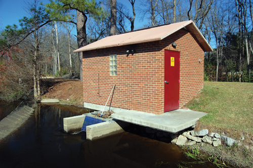
The land is situated near the dam of a 64-acre communal lake, allowing access to the 10 ft. height differential between the lake and the tail water on the other side of the dam.
The amount of water flows over the spillway at an average of 40 cubic feet of water per second, making it a marginally feasible hydroelectric project.
Excavation began on March 4, 2004. By the end of 2006, the underwater portions of the plant had been built, a four-foot aluminum pipe through the back of the dam was in place, the dam was restored, and the temporary cofferdam was removed.
On December 2, 2006, a refurbished 50 horsepower Francis turbine was purchased and installed. The turbine was tested and it was determined that the optimal speed would be 150 rpm. The next step was sizing the electrical generation equipment and designing the automation system.
Designing the Automation System
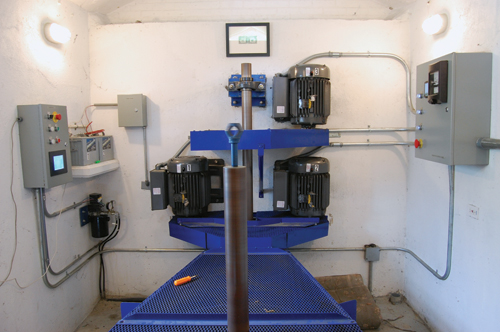
The hydroelectric system is powered by water draining from the lake and through a turbine which drives three generators via a belt and pulley system. The generators are actually three 15hp single-phase induction motors.
When an induction motor is driven at greater than normal speed, it generates electricity. Output from the three motors was tied into the local electric grid via the same transformer that formerly only provided power to the property. The utility’s meter now turns backwards when the plant is supplying more power than consumed by the home and office.
The turbine has an integral control gate that is used to adjust how much water flows through, from 0 to 100%. This control gate was designed to be opened and closed by a 12-inch double-acting hydraulic cylinder, so the first piece of automation equipment installed was a 24 VDC hydraulic reversible pump to operate the gate.
We realized that as a grid-tied induction-based generation system, the generator/motors would freewheel if the excitation current from the grid was lost. We therefore needed to be able to automatically shut down our hydro plant in case of a grid power failure.
When a shutdown signal from the control panel or a fault condition occurs, the shutdown procedure is simply to run the pump in the “close” direction for 60 seconds and to open the contactor to the generators. The hydraulic pump has a built-in pressure relief valve that allows it to safely runa minute or two after maximum extension or retraction of the cylinder.
It was crucial that the system also monitor rpm and shut down based on either over-speed (caused by a disengaged generator or broken belt) or under-speed (insufficient power generation) conditions, so it was time to purchase and install a controller.
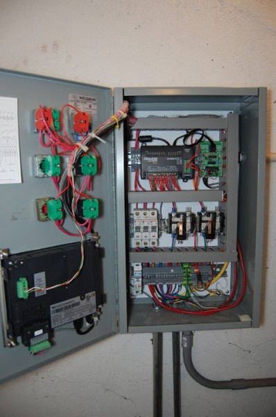
I decided a DirectLOGIC 05 Micro Brick PLC would be sufficient for this purpose. I placed our first order with AutomationDirect for the PLC, a proximity sensor to count shaft revolutions, a NEMA 1 enclosure, and various pushbuttons, terminals, DIN rail and wire ducting. After a couple of weeks of learning ladder logic, I began to install the basic automation system.
A local bearing distributor determined what belts, sheaves and shafts were needed to transfer rotation of the turbine to the three induction motors. In early February 2008, the first kilowatts of power were generated.
Using only the demo version of the DirectSOFT 5 programming software, which limited me to 100 instructions, I programmed the DL05 for the following operations:
• an always-running “monitoring” stage that counts revolutions and calculates rpm
• a startup stage that activates upon pushing the startup button, opens the turbine, and engages the motors at the prescribed RPM
• a shutdown stage which fully closes the turbine and disengages the motors.
The shutdown stage was triggered by any one of three conditions: the shutdown button being pushed, an auxiliary contact on the motor contactors opening (meaning ac control power was interrupted), or RPM out of normal operating range.
Making, Measuring and Monitoring Power
In May 2008, we signed an interconnection agreement with Mid-Carolina Electric Cooperative (MCEC) and its supplier, Central Electric Power (CEP). In June 2008 we began feeding power into the grid.
Throughout the summer, we started and shut down the plant manually, taking into account the lake level and the utility time-of-use tariffs.
The utility paid us nearly twice as much for power generated during the peak demand summer hours from noon until 10pm, a financial incentive that remains to this day.
Later that summer, we bought and installed a submersible water level sensor to monitor the lake level. This 4-20mA device was wired into an AutomationDirect 4-channel analog current input module which we added to the DL-05 PLC. We also bought the full version of DirectSOFT 5 software to add needed capacity and programming capabilities.
I was now able to program the system to automatically shut down when the lake level fell below a certain point. I also added an auto-start function that started generation whenever the level rose above the spillway in the dam. Again, this arrangement worked well, but we also needed to know how much power we were producing.
To do that, we purchased an AccuEnergy Acuvim II panel-mounted power meter. By installing the meter and an AutomationDirect RS-232/ RS-485 converter, I was now able to poll the power meter over Modbus to determine not only volts and amps but also instantaneous kW, cumulative kWh produced, the power factor, frequency and other relevant power parameters.
However, all this time I was only able to see these operating parameters by remotely logging into the computer and looking at the “data view” window of the DirectSOFT 5 programming software. I was also able to do some rudimentary remote control such as starting or shutting down the plant, but it certainly wasn’t user friendly.
At about this time, AutomationDirect announced that the C-more touch panels had IP-based remote operation capability and a built-in Web server. I purchased a C-more panel, installed it, and began learning how to program it with the C-more programming software. By April 2010, I had four screens of valuable information and graphs that could be accessed not only in the power plant, but also computer via a web browser.
To avoid running an Ethernet connection 100 feet between the power plant and house, I installed an inexpensive Asus WL-220gE portable wireless adapter (powered from a USB port on the C-more panel) in the window of the hydro plant building.
AutomationDirect proved to be a valuable asset to this project in many ways. Their easy-to-use Web site has free, comprehensive, and well-written documentation for each item in their catalog, which helped me design the automation system and select the components.
Return on Investment
Depending on rain and how much electricity is used by our home and office, we make between $30 and $300 per month in direct revenue from the power company. This does not include the savings on the power bill, which has gone down from almost $1,000 to around $300 each month.
With the micro hydroelectric plant making about $900/month, this means that in three years, we’ve recovered about $30,000 of our $70,000 investment. Only five more years are needed to completely pay back the investment.
Beyond the financial benefits, we now have the satisfaction of owning and operating our own hydroelectric power plant, as well as the pride of knowing we’re contributing to a sustainable environment.
By Joel Froese
Disclaimer: AutomationDirect does not guarantee the products described in this article are suitable for your particular application, nor do we assume any responsibility for your product/system design, installation, or operation.
Originally Posted: Sept 1, 2011


