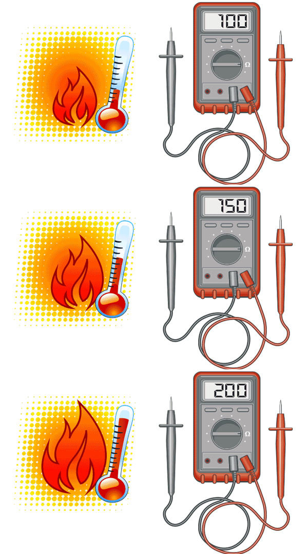
I’d be willing to bet that the majority of you have come across temperature sensing in some way throughout your industrial automation career. Any takers? I’ll give you 3-to-1 odds! You’d be smart not to take that bet since temperature is one of the most measured parameters in automation. But how does it work? How are temperature signals created? To answer that, let’s look at two of the most commonly used temperature sensors in our industry, the Resistance Temperature Detector (RTD) and the Thermocouple.
Resistance is Not Futile
RTDs are devices with an internal resistance that changes wih temperature in a predictable, linear way. They are typically made from a very fine wire wrapped around a ceramic or glass core, or they can be created using thin film technology. Traditionally, platinum, copper, or nickel wire is used and is wound to achieve a specific resistance value. This resistance value will change as temperature does and by supplying a constant current, the measured voltage drop across the resistor can be used to determine the new resistance, and thus the temperature.

RTDs come in a variety of types, with the most common being a Pt100. It’s made from platinum that has been calibrated to be 100 ohms at 0 degrees C. Platinum is an ideal metal for RTDs because of its stability, resistance to corrosion, and higher melting point. RTDs are great for applications up to around 600 degrees Fahrenheit. They provide accurate, repeatable results over the long term, but they are also fragile, have a long response time and are bigger than thermocouples.
The Thermocouple Option
For wider temperature ranges up to a couple thousand degrees, you’ll need to use a thermocouple. Thermocouples work based on the Seebeck effect – a phenomenon where a small voltage is produced across a junction of two dissimilar metals when exposed to a temperature gradient. This is believed to be a result of heated electrons in the warmer metal traveling toward the colder area because of their thermal energy.

The amount of voltage produced within the thermocouple is very small, usually millivolts, and is directly related to the difference in temperature across the junction. There are numerous types of thermocouples and each is represented by a letter. The most common ones are J, K and T which designate a specific temperature range and the wires of each type are color coded to identify them.
See What’s Cooking…
From curing ovens to milk pasteurization, temperature sensing and control has become an important part of automation. If you would like to know more about temperature in automation, check out our newest chapter on Temperature Sensing in the Automation VIDEO Cookbook. There you’ll find many informative videos that discuss topics such as:
- How selecting the right temperature transmitter can improve your remote temperature measurement.
- How to use temperature sensing with our PLC families.
- Helpful information to use when navigating the huge variety of probe styles.
- Tips and tricks to help you get the most out of your temperature sensing application for the least amount of money.
For more articles on process sensing and control, click here.


