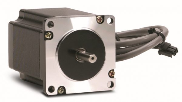
A stepper motor (sometimes called a step motor or stepping motor) is a DC motor with a fixed number of steps that make a full rotation. The motor can be commanded to move to any one of those step locations and hold position without any need for a position sensor – assuming it is properly sized with regard to the torque and speed requirements of the application. This is known as “open loop” control.

Stepper motors are controlled by alternately energizing the windings in the motor. Stepper drives are used to control the high-power DC pulses to the motor, and thusly to control the motion of the motor’s shaft with great precision.
Two-phase stepper motors can be unipolar or bipolar. While unipolar motors are popular with hobbyists, most industrial stepper motors are bi-polar. Bi-polar motors are more efficient and powerful for a given weight.
How many steps per rotation?
The number of steps per rotation depends on the number of windings in the motor. SureStep® motors provide 1.8 degrees of rotation per “full step”, and consequently 200 full steps are required for one complete rotation. But stepper motors can also be controlled with fractions of a “step”, such as “half step”, “quarter step”, etc., a technique whereby the stepper drive energizes alternate windings at high speed to achieve intermediate positions between the full steps.
Microstepping
Most modern stepper drives are capable of “microstepping”, and some even use sine-cosine waveforms to the windings to achieve very high step counts of 10k, 20k or even 50k steps per rev or higher. This value is usually user selectable via dip switches on the drive or via programming software. The available torque of a stepper motor can be significantly reduced when microstepping is employed (SureStep® torque/speed curves are provided at half-step resolution). It should also be noted that step size repeatability and accuracy can suffer at very high microstepping resolutions.
Is a Stepper Motor just one part of a Stepper System?
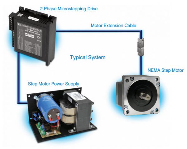
Yes, although in high-volume commercial applications (especially with smaller size motors), the stepper drive may consist of a simple chipset, which may be custom integrated with other board-level control electronics. However, in most industrial control applications the motor is controlled by a dedicated stepper drive, and an unregulated DC power supply provides anywhere from 24 to 80VDC to power the system. These common-off-the-shelf (COTS) components have many obvious advantages in low-volume settings.

How do I control a stepper system?
Stepper drives accept low-power control signals from a PLC or other motion controller and generate the appropriate winding current accordingly. The control signal inputs to the stepper drive are known as “Pulse and Direction” signals. One discrete input controls the direction of the motor shaft, while a second high-speed input is toggled for each step (or microstep) of desired motion. Note that high-speed motion at high-microstepping resolution can require a VERY high-speed pulse train – for example, when microstepping at 50,000 steps-per-rev a step drive would require a 250kHz input pulse frequency to generate a modest 300rpm at the motor shaft (300 rev/min ÷ 60 sec/min × 50,000 steps/rev = 250,000 steps/sec). Depending on the capabilities of the PLC or motion controller a tradeoff between top-speed and high-resolution may be required. Some drives even support changing the microstep resolution on-the-fly, so that high-speed moves can be commanded at low resolution – while improved accuracy is possible at lower speeds.
Homing
For position based applications a home sensor is usually required. On power-up, the controller initiates a homing sequence, and the system determines the home position of the shaft or the connected mechanical apparatus. Most intelligent stepper drives support a number of homing routines (with minor variations) which will cover a majority of application requirements.
Position Verification
In many applications, it is prudent to verify position at least once on each machine cycle. This can be as simple as a ‘move complete’ sensor, triggered at the end of a repetitive motion. Even with a properly sized motor, there may be unexpected obstacles, friction, or other load disturbances that cause the motor to “skip steps”. Due to the open-loop nature of the stepper system, the drive will be unaware of these “skips”. In such cases the controller may need to send additional “steps” to make up the difference – or the homing routine may need to be repeated.
Speed and Performance
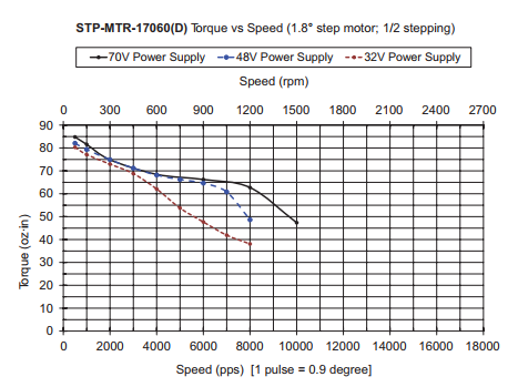
In terms of pure speed, most stepper motors can spin up to 1500rpm or faster – but the available torque falls off significantly at 75% (or less) of the top speed. The sweet spot for stepper motor speed and torque is usually in the 0-500rpm range or below – the torque/speed curve for the specific motor should be carefully considered when specifying the system. Here is a typical example of the torque/speed curves for a SureStep® stepping motor at three voltage levels.

For high-performance applications requiring fast dynamic response, steppers can be extremely effective, but only if the system is designed without a large inertia mismatch between the inertia of the load and that of the motor. If high dynamic response is important in your application, strive to keep the inertia mismatch below 10:1. For the highest performance – aim for 1:1.
Consider a gearbox

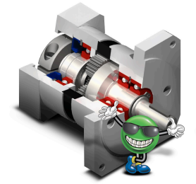
Gearboxes are often employed to help reduce inertia mismatch and to further increase the effective torque of a stepper motor. AutomationDirect offers the SureGear® line of precision planetary gear reducers that mate directly to our NEMA frame SureStep® motors (we even include the mounting hardware). These gearboxes offer a wide range of ratios (5, 10, 25, 50, and 100:1), low backlash of 30 arc-min or less, and they are maintenance free; requiring no additional lubrication throughout their service life of 20,000 hours.
Gearboxes reduce the reflected inertia of the load by the square of the gear ratio. This can offer dramatic improvements in inertia mismatch, but you do have to consider the added inertia of the gearbox itself. The gear reduction also limits the top speed of the application.
What are some other stepper motor features to look for?
Frame Size
NEMA frame sizes are common for industrial stepper motors, SureStep® stepper motors are available in NEMA 17, 23, and 34 frame sizes in a number of stack lengths and torque ratings. The length of the stack (body length of the motor) is one factor in determining the available power. SureStep motors are also available in a special “Higher torque” H-series, with stronger magnets and higher power windings for the most demanding applications.
Dual Shafts
All SureStep motors sizes are available with single or dual shafts. Dual shaft motors (actually it’s a single shaft that protrudes from both ends of the motor) are used for driving two independent loads or for the possible addition of a feedback device (when closed loop operation is required).
Connection Type
Connectors are also provided on all SureStep motors. The motors have a 12 inch lead with connector. An inexpensive motor extension cable is used to complete the wiring. This assures that the motor lead connections are correct, and makes replacement of a damaged motor much easier.

