Contactor Definition
Contactors are a specialized form of relay capable of switching higher power loads such as motors, lighting and electric heaters.
Turning large electrical power loads such as motors, lighting and heaters on and off is a common automation requirement. Applications are found in commercial buildings, industrial equipment and vehicles. The fundamental device for switching electrical power is called a contactor. Contactors are basically beefed-up relays, but with some specialized features for handling high power loads.
A previous post has already discussed control relays in detail. This blog post covers why contactors are used, how they work, the terminology involved, some key features and where they are typically installed.
Why are Contactors Used?
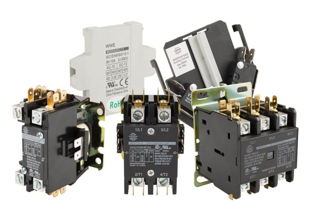
Contactors are used for high power applications. They allow a lower voltage and current to switch a much higher power circuit, so they are generally larger and more heavy-duty than control relays, enabling them to switch higher power loads on and off for many thousands of cycles (Figure 1). Standard control relays typically have contact ratings of 10A or less at 250Vac or less. Contactors, on the other hand, carry much higher contact ratings up to many hundreds of amps, and are commonly rated for operation at 600Vac.
A very common category of electrical contactor includes devices designed to meet International Electrotechnical Commission (IEC) standards, which is predominant in Europe but also used in North America. IEC contactors feature a compact and modular configuration, with many electrical sizes available (Figure 2). End users always need to ensure that any components they select meet the application needs, carry any other required ratings such as UL, and comply with all applicable codes and regulations in service.
Note that some control relays are rated at more than 10A, and some contactors are rated for less than 10A. Technically, a control relay may be able to switch some power loads, and a contactor could be used for control duty. However, best practice is to use devices suited for the intended service.
How Do Contactors Work?
Standard contactors are electro-mechanical devices just like relays, with an electric solenoid coil arranged to close the mechanical contacts when energized. Typical contactors incorporate a spring mechanism just like relays do, but it is larger and more powerful to positively open the load-carrying contacts when the coil is de-energized. Otherwise high current can cause a failure of the contacts to open if they weld together.
Also, due to the larger loads there is more arcing as the contacts are opened. Therefore, contactors have provisions to guide the arc away from the contacts to quickly quench or suppress the arc and preserve contact life. More specialized devices called vacuum contactors can be used for switching voltages higher than 600Vac because arcs extinguish quickly in a vacuum.
Contact Configurations and Applications
Another difference between relays and contactors is in contact arrangements. Control relays are available with varying counts of N.O., N.C. and/or N.O./N.C. contacts to perform a wide range of duties, and relay can operate much faster than contactors.
Contactors, on the other hand, are typically used to turn power on when energized. Therefore, contactors usually offer N.O. for the main power contacts, also known as poles. Certainly, there are contactors with N.C. contacts, and sometimes each contact is a replaceable cartridge. Here are some contactor power pole arrangements, with a common application for each (Figure 3):
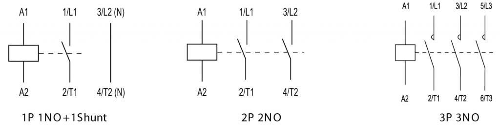
- 1-pole: for operating a 12Vdc load on a vehicle
- 1-pole+shunt: for operating a 2-wire 1-phase 120Vac load like a fan (the pass-through shunt connection is not switched and is provided for wiring convenience)
- 2-pole: for operating a 3-wire 1-phase 240Vac load like a residential air conditioner
- 3-pole: for operating a 3-wire 3-phase 480Vac load like an industrial motor
- 4-pole: for switching all phases and the neutral for a 3-phase load
Contactors may be used to turn loads on and off frequently. Other times, they are part of an emergency stop circuit where they may remain energized for long periods of time to provide main power to equipment, but will de-energize the equipment if the emergency stop circuit is activated.
In addition, it is sometimes desirable for control circuits to interface with contactors, but it would be wasteful to consume a contactor power pole for a small control circuit. Therefore, most contactors offer add-on auxiliary contacts which mount on the side or top and offer many more control contacts in various configurations (at much smaller ratings, usually below 10A) for control wiring purposes. Specialized contacts are capable of passing smaller currents and voltages due to the contact material and design, with high holding pressure and very low internal impedance.
Many IEC contactors can accept several adder decks of auxiliary contacts for top mounting. If numerous control circuits require switching, these are a good option to accomplish this instead of using many control relays in parallel.
Electrical Ratings
Refer to What Is A Relay? for more details regarding relay and contactor electrical terminology. It is important to review the specification sheets for both to ensure the contact will perform as needed. Some contacts are rated differently for certain loads, the two main types being:
- Resistive: typically used with heaters and incandescent lighting
- Inductive: typically used with motors, solenoid coils, or transformers
Since contactors often operate motor loads, it is common for manufacturers to provide tables relating to how much horsepower can be operated, along with the full load current of the contactors for various normal operating voltages. This helps user select the right size. Also, IEC lists many utilization categories identifying typical applications to assist users with selecting a contactor. Note that each relay or contactor may have different ratings based on UL or IEC standards. Power poles will have different ratings than auxiliary poles.
When contacts are rated for DC loads, it will usually be for a much lower amperage than for an AC load. Higher AC loads can be interrupted by contacts because AC circuits experience rapid zero-volt-crossings, making it easier to extinguish the arc.
Since contactors are larger than relays, they usually have higher power consumption and heat generation, which must be considered when designing the enclosures in which they are housed. Also, the control circuit should be carefully designed to supply sufficient coil voltage or the contactor may chatter.
Contactor Installation
Contactors are usually selected, sized and ordered by their intended full load amperage. It is usually OK to oversize a contactor, but never to undersize it. Some users try to limit their selections to minimize the number of parts ordered, even if they oversize a component once in a while.
Small contactors may use DIN rail mounting, and some contactors use their own specialized mounting plates or can simply be panel-mounted. Bigger contactors are quite heavy and usually must be bolted to an enclosure backpanel. Note that while industrial relays often are removeable and plugged into permanently wired bases, this is not usually the case with contactors. Contactors are typically mounted and wired into place and must be unbolted and unwired when replaced (Figure 4). Sometimes a contactor can be disassembled from the front for replacing certain parts.
Most small relays are designed to be IP20 touch-safe as are some newer contactors, especially IEC versions. However, many larger contactors will have open-style configurations requiring separate terminal covers. Wires are either landed into compression lugs, or sometimes lugs must be installed onto the wires so they can be landed on bolted connections. Some vendors offer ready-made jumper bars to speed electrical installation for various configurations. Other helpful features are clearly marked connections and model number, and a means to easily apply nameplates or markers.
One final note regards using contactors with PLC discrete outputs. If a small contactor is to be directly controlled by a PLC, then a coil surge suppressor should be installed on the contactor to protect the PLC output from failure. For larger contactors the coil is likely too big to be energized by the PLC directly, so a PLC relay output or an interposing control relay may be needed. Many manufacturers offer electronic coils on larger frame contactors, which reduce the energizing current allowing for direct control without an interposing relay.
Contactors as Motor Starters
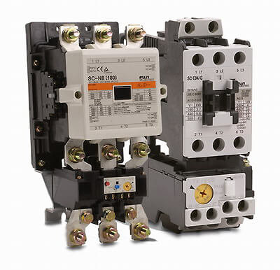
Motors are a special category of load, and the NEC has certain requirements for overcurrent and overload protection of motors. When a contactor is used for motor control, it is typically combined with an overload relay to provide better protection for the motor and feeder wiring. Contactors paired with an overload relay in this way and used in motor control service are often called starters (Figure 5). If a contactor is bought as an assembled package with an overload relay, it may be called a combination starter.
Contactors are versatile devices used widely in a variety of industries. Although simple in concept, there are many nuances that must be understood to properly specify and apply contactors. This blog post is a good starting point, with further information available from AutomationDirect’s experts.
Read more articles related to contactors here!
Originally Published: July 2019