A motor starter is a combination of devices used to start, run, and stop an AC induction motor based on commands from an operator or a controller. In North America, an induction motor will typically operate at 230V or 460V, 3-phase, 60 Hz and has a control voltage of 115 VAC or 24 VDC. Several other combinations are possible in North America and other countries and are easily derived from the methods shown in this document.
Motor Starter
The motor starter must have at least two components to operate: a contactor to open or close the flow of energy to the motor, and an overload relay to protect the motor against thermal overload. Other devices for disconnecting and short-circuit protection may be needed, typically a circuit breaker or fuses. Short-circuit protection will not be shown in the examples that follow.
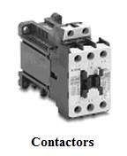
Contactor
A contactor is a 3-pole electromechanical switch whose contacts are closed by applying a voltage to its coil. When the coil is energized, the contacts are closed, and remain closed, until the coil is de-energized. The contactor is specifically designed for motor control but can be used for other purposes such as resistive and lighting loads. Since a motor is an inductive load the designer must consider both horsepower and current ratings when specifying the size of a contactor. This is to ensure the contactor will properly switch the load.
Overload Relay
The overload relay is a device that has three current sensing elements and protects the motor from an overcurrent. Each phase going from the contactor to the motor passes through these current sensing elements. The overload relay has a selectable current setting based on the full load amp rating of the motor. If the overload current exceeds the setting of the relay for a sufficient length of time, a set of contacts opens to protect the motor from damage.
This article shows how to wire various motors using the Fuji series of contactors sold by AutomationDirect. Other brands of contactors may be wired the same or similarly. Consult the manufacturer’s wiring diagrams for other brands of contactors.
There are four basic wiring combinations:
a) Full-voltage non-reversing 3-phase motors.
b) Full-voltage reversing 3-phase motors
c) Single-phase motors
d) Wye-delta open transition 3-phase motors
You must supply a disconnect switch, proper sized wire, enclosures, terminal blocks and any other devices needed to complete your circuit.
WARNING! Follow the instructions supplied for each specific device.
Failure to do so may result in electrical shock or damage.
The following components will be used:


Full-voltage non-reversing 3-phase motors
The following diagram depicts 3-phase non-reversing motor control with 24 VDC control voltage and manual operation. We will use a contactor, an auxiliary contact block, an overload relay, a normally open start pushbutton, a normally closed stop pushbutton, and a power supply with a fuse. The start and stop circuits can also be controlled using PLC inputs and outputs.

Full-voltage reversing 3-phase motors
This diagram is for 3-phase reversing motor control with 24 VDC control voltage. It uses two contactors, two auxiliary contact blocks, an overload relay, a mechanical interlock, two normally open start pushbuttons, a normally closed stop pushbutton, and a power supply with a fuse. The forward, reverse, and stop circuits could alternatively be controlled using a PLC. Note that Reversing Kits for both the load and line side of the contactors may be available and may simplify the process of wiring a reversing contactor.

Full-voltage single-phase motors
This diagram is for single-phase motor control. It uses a contactor, an overload relay, one auxiliary contact block, a normally open start pushbutton, a normally closed stop pushbutton, and a power supply with a fuse. The start and stop circuits could alternatively be controlled using a PLC..

Wye-delta open transition 3-phase motors
The following diagram is shown for 3-phase motor control of a delta-star connection. It uses three contactors, an overload relay, one auxiliary contact block, a normally open start pushbutton, a normally closed stop pushbutton, an on-delay timer of 0-20 seconds and a power supply with a fuse. The start, stop, and timing circuits could alternatively be controlled using a PLC.

THIS INFORMATION PROVIDED BY AUTOMATIONDIRECT.COM TECHNICAL SUPPORT IS SUPPLIED “AS IS” WITHOUT A GUARANTEE OF ANY KIND. We do not guarantee that the data is suitable for your particular application, nor do we assume any responsibility for them in your application.
The Technical Support page on the AutomationDirect website is full of valuable information and is available 24/7. This is referenced from the Technical and Application Notes section.