Part One of this series (in Fall 2011, issue 21) started with a complete reference to the technical information available from AutomationDirect that can help you understand and select components from the SureStep family for an open-loop motion application. It also reviewed the hardware methods for controlling your system, including PLC high-speed I/O or counter modules. Part two discusses the serial communications control method and includes additional reference document links.
 ASCII Serial Communications Control
The second method for control is done by taking advantage of the advanced stepper drives’ ability to accept ASCII data commands via RS-232 serial communications. This method is supported from certain serial ports of all DirectLOGIC PLCs, CLICK PLCs, and the Productivity3000 Programmable Automation Controller. Review the instruction set for the specific PLC and investigate the instructions that can produce the ASCII data commands. Then confirm which RS-232 serial communications port is supported by those instructions, usually configurable as an ASCII port.
The complete SureStep Advanced Microstepping Drive SCL User Manual is available at: http://bit.ly/p5p2GA
The user manual covers the SureStep Pro configuration software, communications, and describes each serial ASCII (SCL) command in detail. A helpful application note has information and examples on using the various SCL commands, found here:
http://bit.ly/qqdoq8
The application note details many ASCII SCL commands and gives examples of various types of moves that can be executed using them.
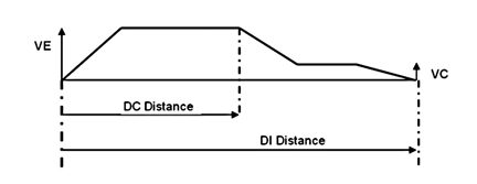
Here is an example, with comments, of the ASCII commands that would be used to perform a basic move sequence called the FC Move. This move is sometimes called a “blended” or “high-speed/creep” move. It is fully defined as “Feed to Length, with Speed Change”. Its sequence of operation is as follows:
Accelerate up to a certain speed, and continue at that velocity until reaching the “DC” (Distance Change) value. At this point, it will decelerate to the VC (Velocity Change) value and continue until it nears the end of the move. Then decel and stop when it reaches the DI (Distance) value, which is the overall move length. (Profile shown in Figure 1)
The actual commands are:
1. “MD” “Motor Disable”, always do this when changing Command Mode settings.
2. “CM21” “Command Mode 21”, makes sure the drive is set to Point-to-Point positioning mode.
3. “AC2” “Accel”, sets the accel, which will apply to the starting ramp. Both Accel and Decel are independently adjustable, if desired
4. “DE2” “Decel”, sets the decel, which would apply to both changes decel ramps.
5. “VE3” “Velocity”, sets the peak velocity of the move.
6. “EG1000” “Electronic Gearing”, sets pulses per rev
7. “ME” “Motor Enable”, enables the motor for motion
8. “DI90000” “Distance”, this is the overall move distance
9. “DC60000” “Distance Change”, this is the point during the move at which the velocity will change.
10. “VC0.5” “Velocity Change”, this is the second velocity (typically lower than VE) which the drive will go to after it reaches the DC length.
11. “SA” Saves the parameters in the drive.
An “FC” command initiates the move. After the other settings are loaded to the drive, this is the only command required for the drive to execute the move.
The “Intro to Motion Control” tab at the bottom of the application note has some very useful information about point-to-point and absolute positioning. (Note the series of tabs with additional special topics.)
As an example, the CLICK PLC currently does not support high speed inputs and pulse outputs, nor is there a CTRIO module available for the CLICK. But with the use of a SureStep advanced microstepping drive, the CLICK can be programmed to send SCL commands to the drive in order to perform motion. In the case of the CLICK PLC, we can use the “Send” instruction to put together an ASCII string of data that can be communicated to the advanced drives. Page 4-29 in the CLICK PLC Hardware User Manual shows an example of ASCII “Send” instruction programming. The CLICK user manual is available at:
http://bit.ly/nx7Fe6
The Online Help file for the CLICK PLC has additional details on using the “Send” instruction, and the free programming software can be downloaded at:
http://bit.ly/ox2FTJ
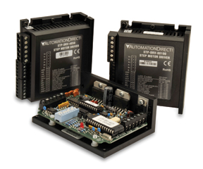
Any DirectLOGIC PLC capable of RS-232 ASCII communication can write serial commands to the SureStep advanced drives (STP-DRV-4850 and -80100). These PLCs include DL05, 06, 250-1, 260, 350, and 450 models.
However, we strongly recommend using DL06 or D2-260 based PLCs for serial commands due to their more advanced ASCII instruction set, which includes PRINTV and VPRINT commands.
The advanced microstepping drives include the SureStep Pro configuration tool on CD. It can also be downloaded online at:
http://bit.ly/oa3kIE
The software can be used for easy configuration and setup of the drive, its control mode, I/O and attached motor.
The Online Help file included with the software will help in understanding all the features that can be set up, configured and tested with the tool. The software’s built-in command line is terrific for testing and troubleshooting SCL commands.
Additional Information
The following links are additional information that you may find useful when working with the SureStep Stepping System and related controls:
AutoCAD ™ Template Drawings:
http://bit.ly/nZxzbf
Look for SureStep Stepping Systems under the Drives, Motors and Motion Control category. The zipped file size is 0.97 MB.
FAQ’s:
http://bit.ly/pBKeZx
There are several FAQs that may help answer some of your questions.
View the AutomationTalk webinar on Motion Control with Micro PLCs at:
http://bit.ly/oiC33S
This webinar features a DL05 PLC with an H0-CTRIO High-Speed Counter Module interfaced to a SureStep stepping motor, drive and power supply. The motor is coupled to a linear ball screw slide. The tutorial reviews the use of the CTRIO Workbench configuration software utility to create profiles. It also covers the supporting ladder logic and using a C-more Micro-Graphic touch panel to execute a homing profile, velocity profile, trapezoidal profile, and jogging.
Read Part One here: http://library.automationdirect.com/starting-with-steppers-part-one-of-a-two-part-series-issue-21-2011/
By Tom Elavsky,
AutomationDirect
Originally Posted: March 1, 2012


