If you can’t buy it, you have to build it. This was the situation our group of engineering students encountered when we needed to grow vascular tissue for a bioengineering project at Walla Walla University, and found existing solutions were not acceptable.
In addition to our team, others needed the machine for their research projects, which provided additional motivation.
We built a new machine to meet our needs, and anyone involved in tissue engineering or biomaterials research at a university or a biotech company might find our method of nanofiber production (electrospin machine) particularly useful.
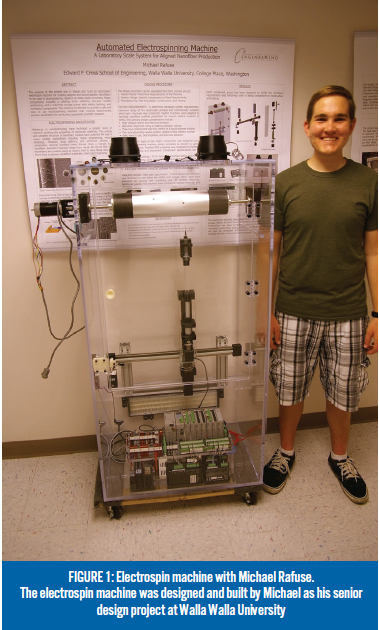
The electrospin machine is located at Walla Walla University (WWU), a private university founded in 1892, and home to the Edward F. Cross School of Engineering. The construction of the machine was initiated by Michael Rafuse, a graduate of WWU. The machine was his senior project, and he did the majority of the mechanical and automation system design, build and commissioning of the machine. I installed the operator interface, programmed the motion system and operator interface, and performed some experiments to optimize the machine for our polymer solutions.
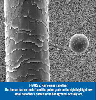
This is not a new process. Electrospin machines are widely used in the research community for producing fiber mats for culturing cells. These mats consist of tiny polymer nanofibers, each mere nanometers in diameter ( as shown below), which mimic the human extracellular matrix by providing a 3D structure, called a scaffold, where cells can grow into human tissue. The electrospin machine is used to make these scaffolds, which are then used to fabricate tissue engineered vascular grafts.
Scaffold Construction
The electrospin machine uses a rotating drum collector to create a biocompatible aligned nanofiber mesh. Features include a syringe and needle automatically positioned in horizontal and vertical directions, and a tube-free syringe pump. The machine provides a safe and simple interface for operation, and can be quickly modified as required.
Electrospinning requires high voltage, a grounded collection surface and a polymer solution to produce fibers as small as nanometers in diameter. The polymer solution is loaded into a syringe with a blunt-tip needle and a high voltage electrode is attached to the metal tip. The syringe is set at an adjustable distance, typically 20 cm away from a collection surface.
The collection surface is a rotating drum that is connected to an electrical ground. When the high voltage source is turned on it creates an electric field that induces a charge in the polymer solution, and repulsion forces propel the polymer solution towards the grounded collection surface. As the polymer flies through the air, the solvent evaporates and leaves a fine fiber that is mostly dry when it reaches the collection surface.
A two-axis gantry configuration holds the needle and is positioned using stepper motors. One stepper motor is used to control the vertical distance between the collection surface and the needle tip, and a second is used to control the horizontal position of the tip. A third stepper motor is used to control the extrusion rate of the polymer solution flowing through the needle tip. The collection surface rotating drum is the fourth axis of the machine, and it is spun at speeds up 4000 rpm using a brushless DC motor.
Machine Control Components
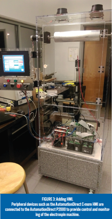
The main automation system components are all AutomationDirect products and include a Productivity®2000 programmable controller, a C-more EA9 series 10” touch panel human machine interface (HMI) and SureStep® stepper motors and drives. The controller, HMI, stepper motion control and related linear actuators enable precise and configurable control of the electrospinning process. AutomationDirect’s Rhino power supplies (5V, 12V, and 24V), GCX series selector switches and pushbuttons, and ECX series indicator lights were also used.
The controller has a high performance CPU with plenty of memory, five communication ports including USB and Ethernet, and can control up to 480 local I/O points. We programmed it using AutomationDirect’s free Productivity Suite programming software. This software allows user-defined tag-based programming for easy I/O naming, and provides task-based organization of ladder logic code. The electrospin process is primarily viewed and adjusted using the HMI. Several buttons, switches and indicator lights are also provided for control and status indication.
Variable Electrospin Control
Many of the variables affecting the process and resulting fiber production are adjustable via the HMI. Variables need to be finely tuned to create consistent nanofibers with a particular surface morphology to meet research or application requirements. The rotating drum collector speed, needle positioning and syringe pump are the critical systems. Closely monitored and controlled and commonly modified variables include collector surface speed, needle-to-collector distance, polymer solution flow rate, and high voltage level.
The drum collector is rotated using a brushless DC motor and drive. Drum speed is set by a 0-5 VDC analog output from the controller, and direction is controlled via a discrete output. Speed control is closed loop, with feedback provided by hall-effect sensors. Drum starting and stopping, along with speed adjustment, is performed with the HMI.
Needle positioning can be varied using the horizontal belt drive and vertical screw drive slide table systems. Stepper motors power the slide tables and provide precise positioning control for horizontal and vertical movement. Horizontal and vertical travel distances are 50 cm and 25 cm respectively.
The distance from the needle to the collection surface is one of the most significant variables in the electrospinning process. Position of the needle is controlled using a high-speed output module.
The syringe pump is the third critical system, and it consists of an electrically isolated syringe mount with precision adjustable flow rate control using a stepper motor and linear actuator. It is attached to the vertical screw-driven needle position slide.
The syringe pump uses a stepper motor and linear actuator to precisely control plunger movement; end-stop switches are installed in the linear actuator. Syringe flow rate is controlled using step signals sent from the controller to the stepper drive. Its target position is controlled using the HMI, and flow of the polymer solution is adjusted to maintain a droplet at the needle tip for uniform fiber deposition.
Final Results
My part in the project included wiring of the peripheral equipment, controller programming and related tasks. Some mechanical fine tuning, primarily balancing of the rotating drum, made the machine operational. I then spent much of my time refining the stepper motor control logic and optimizing the electrospin process parameters. After taking the time to learn how best to operate the control system, and with some persistence, we’ve been running the equipment successfully since spring of 2016.
Ralph Stirling, the WWU professor involved with this project, comments. “The AutomationDirect Productivity 2000 controller and C-more touch screen are both fantastic units. I would love to upgrade all the controllers I use in my class to Productivity 2000s as they are significantly easier to program, especially for stepper motor applications.”
The benefits of the new machine are significant and measurable. Larger and thicker fiber mats can now be produced, and our production rate has increased. The machine can also be modified to test different collection methods. With extensive testing of the machine in progress, much more fiber will be produced in the near future.
By Thomas Lemon, Bioengineering major at Walla Walla University in College Place, Washington
Originally published: Sept. 21, 2016