A steady supply of clean and dry air is required to protect all the pneumatic components in machines, equipment and processes and to ensure their proper operation. While controlling mechanical motion with pneumatics—such as clamping, positioning, pushing and lifting—is often the focus, clean and dry air with enough flow to provide the required pressure must be designed into the system.
It Starts with Plant Air
From the plant or shop compressor to the machine, compressed air often flows through multiple devices, pipes and fittings that can add particulates, oil and moisture. Even if the main plant compressor includes an air dryer, filter, water separator and regulator, the air should still be prepared at the machine before it is used. Air preparation at the machine can be important if there is a long distance from the main compressor to the point of use where additional water or especially if there is a long distance between them where additional water or particulates could build up. This helps ensure your machine gets the best possible protection and longest possible service life. An air preparation system should include regulators, filters and lubricators, in addition to manual and electrical air dumps for safety.
Ensure Adequate Air Flow
A properly functioning pneumatic system requires a proper supply of plant air. Without adequate plant air, the pressure will sag during use, especially when the machine requires high air flow during operation. Even surrounding equipment and manual air blow nozzles may demand flow and cause pressure sagging. Increasing the size of the supply pipes is a first step to eliminate pressure sag, but the problem can be low pressure all the way back at the compressor or plant air prep system.
It is not uncommon for flow restrictions, leaks and pipe run distance in the plant air distribution system to drop air pressure by 5 to 10 psi. Because of this, it is a good practice to require air pressure at the input to the machine air prep system to be 10-20% higher than the machine operating pressure (be sure the plant air does not exceed the maximum operating pressure for air prep components). It’s also recommended to up-size the supply pipe to the next larger size required by machine flow. If the supply pipe appears to be too small or if there are supply pressure variations, this design guideline probably wasn’t followed.
Getting Prepared
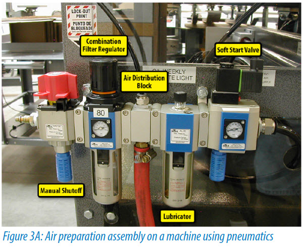
It is not a bad thing to have an oversized air preparation system, as this can leave room for additions or unanticipated demands. The air prep system should start with a manual shutoff relief valve with lock-out to remove air for maintenance. For additional safety, OSHA also requires air to be dumped during an emergency stop or other safety event. For this purpose, an electrical soft start valve that dumps air when power is removed is recommended. The soft start valve also keeps the pneumatic equipment from banging when air is applied.
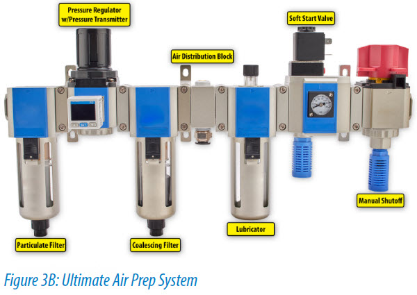
The filter, regulator and lubricator (FRL) is installed just downstream of the manual shutoff relief valve. The air filter provides particulate removal and moisture separation filters in a wide range of port sizes, typically from 1/8” to 1”. Standard filters remove particulate to around 40 μm, while fine filters are available to remove particulates down to 5 μm or less.
These filters are necessary to reduce contaminates and moisture in the compressed air at the machine. All pneumatic components benefit from this, but keep in mind that a filter that is too fine for the application can become blocked quickly. While a 40 μm filter works well to protect valves and cylinders, process instrumentation or high speed pneumatic tools will benefit from a finer particle filtration. Special, finer filters may also be needed for food, pharmaceutical and paint shop applications, and specify coalescing filters if oil vapors or aerosols need to be removed from the air stream.
The air filter bowls often include manual, semi-automatic or automatic drains to remove trapped liquid that has been separated from the air. The manual drain is just a valve. The semi-auto drain is similar to a check valve; it is closed when pressure is applied and opens when pressure is removed. The auto drain automatically opens when the liquid in the bowl reaches a certain level. These removable bowls also allow easy replacement of the filters. A variety of accessories are available to mount these combined filter/separators individually, or to a downstream regulator.
 Pressure Adjustment
The regulator is selected to match the port size of the upstream filter. It adjusts the pressure of the filtered air between a typical range of 20-130 psi, with lower pressure ranges often available for applications needing more precision. Most piloted valves require 30 psi to operate. Pulling the knob up and rotating it changes the air pressure, and this knob locks in the pressure when pressed down.
Equipment design often dictates the required operating pressure. A minimum operating pressure must be maintained, with values below this level sensed by a pressure switch to alert an operator. Although higher pressure than required may make the machine run faster, it can cause excess wear and tear due to the banging caused by fast cylinder motion. While over 100 psi may be supplied to a machine, operating at 60 to 80 psi is usually a good design goal.
Features of note in a regulator are a pressure relieving design and a built-in, integral pressure gauge. The pressure relieving design will relieve pressure if the set point is lowered or if a downstream condition raises the pressure. The only way to reduce the pressure in a non-relieving design is to cycle the downstream equipment. An integral pressure gauge is always a good idea to provide quick indication f system air pressure, and to assist when setting the regulated pressure. The pressure gauge indicates the regulated downstream pressure, not the incoming/upstream pressure.
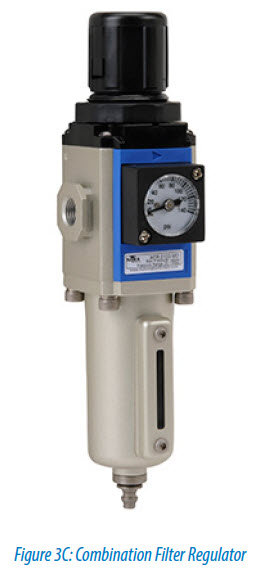
Combination filter regulator air prep units are also available. These units have all the capabilities of the separate filters and regulators described above combined into a single unit. This design can save significant pneumatic panel space if a single regulated air pressure works for the application, and it also saves money.
Lubricate with Care
If needed, a lubricator is installed downstream of the regulator. Often, if lubrication is provided, all machine pneumatic components are lubricated. In this case be sure to match the port size of the upstream regulator to maintain proper air flow. A smaller unit can be used if only a few components need lubrication.
An important question to ask is, “Do I really need lubrication?” Today’s pneumatic devices often don’t require lubrication, but high-speed pneumatic power tools often do, so check the manufacturers’ recommendations. Some devices will need a light-weight non-detergent oil such as SAE 10, ISO VG32, or equivalent lubrication, while some are pre-lubricated and don’t require it.
A mist-type air lubricator creates a fog of oil vapor via an oil drip, needle valve and ejector nozzle, and it should be mounted close to the pneumatic devices to be lubricated. Also note that an oil mist does not generally travel uphill, so mount the air prep unit above all valves and cylinders that require lubrication. Routing of hose and tubing should also be carefully considered.
Lubricators are available in a variety of port sizes to match other air prep components. Due to the adjustable lubrication rate, the bowls are also available in several sizes to store more oil as needed. When the sight gauge indicates low oil level, more oil can be added while the lubricator is pressurized.
Proper design of the plant air preparation system including correct specification of all the required components will ensure many years of trouble free operation for the downstream pneumatic components. When in doubt, it’s generally best to oversize supply lines, as pressure can also be stepped down at the point of use.

A word of advice when a lubricant is used: Valves sticking in the off position or leaking when off, and premature wear of pneumatic cylinders and actuators, are often a sign of dirty or moist air causing seal wear and damage. In some cases, a cylinder could fill with water over time, locking the cylinder. Oil can cause the same results, and oil and contaminates can also clog up valves, especially small pilot ports and mufflers.