For determining the precise motion of industrial machinery and equipment elements, or servo motors, encoders provide a high-performance solution—but only if they are specified properly.
By Joe Kimbrell, AutomationDirect
Mechanical movement generated on automated machinery and equipment almost always needs to be monitored by sensors to provide a robust motion control solution. This is especially the case for servo motor controls in motion control systems, but accurate motion detection is used for other types of applications as well. Sensing devices called encoders are one of the most common devices applied to provide this functionality for industrial applications.
Encoder Basics
Accurately determining the position, velocity, and direction of rotary or linear motion is fundamental for precise, rapid, and sophisticated motion control. Whether the equipment in question is for assembly, packaging, pick-and-place, a rotary table, robotics, or many other applications, the ability to accurately detect motion is crucial. These sensors need to work with high-speed digital controllers, such as specialized motion controllers, variable frequency drives (VFDs), or industrial programmable logic controllers (PLCs) rated for this capability.
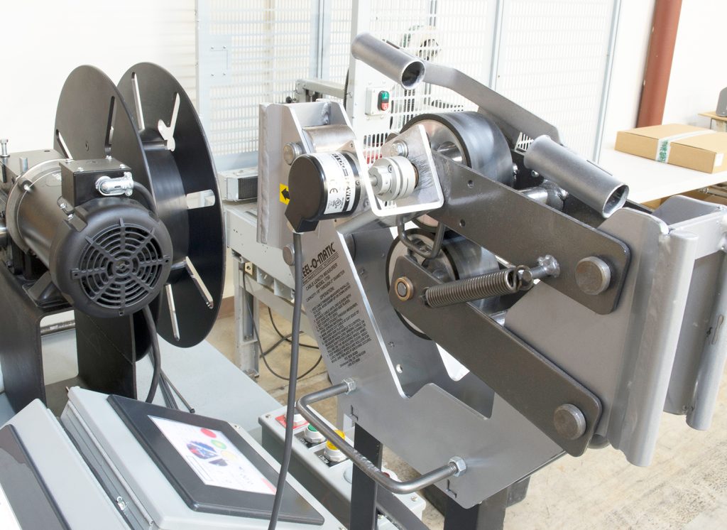
A basic limit switch can identify a single equipment position, and some other technologies such as lasers can detect a range of positions. But to provide comprehensive feedback to a controller, especially on rapidly moving equipment, a much more capable choice is an encoder. An encoder does this by providing high-speed precision electrical signals (pulses or communication) to the controller (Figure 1).

Encoder Geometry and Resolution
Encoders are available in rotary or linear configurations, and the rotary style is often applicable even for linear motion systems because driveshafts, gearboxes, and other rotary elements may form part of the mechanism. Encoders are available in light-, medium-, and heavy-duty versions to withstand various amounts of force and environmental conditions.
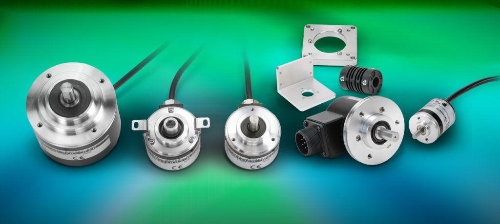
This article focuses primarily on rotary encoders (Figure 2), but many of the concepts are applicable for linear encoders.
- Rotary Encoders: A coded target disc and sensing head internal to the encoder measures rotational motion. The resolution is typically expressed in pulses per revolution (PPR) or lines per revolution (LPR). The term LPR comes from the fact that optical encoders use high-speed optoelectronics to read light through apertures on a disc (Figure 3).
- Linear Encoders: A scale or coded target strip, similar to a tape measure, is read by a sensing head to determine motion along a straight path, with a resolution expressed in pulses per distance, such as pulses per inch (PPI).


More pulses per an amount of motion provide greater resolution.
One-Channel Encoders
For a one-channel (one physical output) encoder rated for 100 PPR, the output will pulse 100 times for one revolution of the shaft, but does not indicate direction.
Two-Channel (quadrature) Encoders
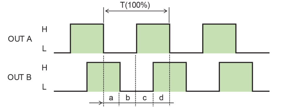
A two-channel encoder—also called quadrature, “times 4”, or “x4”—uses two output channels, oriented 90 degrees apart from each other (Figure 4). Since there are multiple transitions of high and low pulses, the device reading these two-channel encoders can actually determine four times the number of positions of a one-channel encoder. Therefore, a two-channel encoder rated at 100 PPR would have a rating of 400 counts per revolution (CPR). Another great advantage of quadrature encoders is that a digital controller can determine the direction the encoder is turning based on which pulse (A or B) goes high first.

Digital Communication Capable Encoders
The previous examples refer to incremental encoders providing basic hardwired discrete outputs as feedback. Today, there are many encoders that can transmit their information using various digital interfaces such as:
- EtherNet/IP
- EtherCAT
- Modbus TCP
- Modbus RTU
- CANOpen
- Synchronous serial interface (SSI)
- Bidirectional/serial/synchronous (BiSS)
Communication-based encoders typically offer high or higher resolutions compared to quadrature encoders. Comms encoders are normally classified by how many bits of data they use for storing and transmitting position. A 13-bit EtherNet/IP encoder would be able to determine 2^13 = 8192 positions per revolution.
Some versions of these devices—absolute encoders discussed more below—also store how many complete revolutions they have turned. This feature of an absolute encoder allows motion systems to home one time and theoretically not have to be homed/calibrated again. Battery and capacitor backed-up models can track position for months or years, while newer ‘energy harvesting’ models can track the ‘number of turns’ indefinitely (you only have to provide power if you wish to access the position information).
Encoder Sensing Technology
Encoders can be classified based on their pulse sensing technology:
- Optical Encoders: Use light as the detection method. They are capable of high accuracy and resolution but are susceptible to dust, vibration, and contaminants—so must be carefully protected. Optical encoders should be specified with an environmental rating of IP50 (dustproof) or higher.
- Magnetic Encoders: Use a magnetic sensor. This sensor can provide very high resolution, but is typically less accurate compared with optical encoders. They’re more durable and suited for harsh environments, although they can be susceptible to magnetic interference.
- Capacitive Encoders: Use capacitive technology, a relative newcomer compared with magnetic types, and perform similarly to magnetic encoders, but are slightly more susceptible to dust and moisture.
Other Encoder Terms
It is important to select the right encoder options to meet the application needs; following are some common terms:
- Incremental Encoders: These track relative motion by counting pulses, but they only show how far the shaft has travelled, and they do not retain position data when powered off. If the starting position is important, then the automation system must be programmed to start counting when the equipment is at a known “home” point.
- Single-Turn Absolute Encoders: These are absolute encoders that know what angle they are at upon power up, but don’t know how many turns they have accomplished. If that information is important, then the signal needs to be homed, or a multi-turn encoder should be used.
- Multi-Turn Absolute Encoders: These encoders provide the same basic functionality to provide PPR while the encoder is turning, and also have a rating for “turns” (how many turns the encoder can count before rolling over). They use a battery or super-capacitor (or more recently, energy harvesting technology) to maintain and update the count of how many total revolutions have been made by the encoder shaft even if power to the encoder is off.
- Z-Pulse or Index Channel: Some incremental encoders generate an additional pulse output when the disc crosses a fixed zero position. This signal can be used to reset a revolution counter or provide precise homing.
- Gray Code: This is an alternate scheme, as compared to standard binary code, which ensures only one signal line changes at a time, so that a controller is less likely to decode erroneous data.
- Electrical Output: Absolute encoders with discrete outputs (Gray Code, binary, etc.) can work with general-purpose controller inputs, but discrete incremental encoders produce high-speed pulse streams and generally must be wired into high-speed controller inputs of the appropriate type. Some types of high-speed signaling are line driver, NPN open collector, push-pull (totem pole), HTL, and TTL.
- Speed Limitations: Encoders are subject to both mechanical speed limits (the actual max physical speed the encoder can be turned) and electrical speed limits (the speed that discrete outputs can transition), so designers must ensure the application remains below both these limits by an acceptable margin.
High-Performance Position/Velocity/Direction Detection
When used with a typical PLC, servo motor controller, or other controller, an encoder is often the best way to precisely determine the position, velocity, and direction of equipment motion. Selecting the appropriate encoder requires consideration of various factors as listed above, plus others in some cases. Users also need to understand how these elements work together to ensure the encoder meets the specific needs of the application by providing accurate and reliable motion feedback.
The AutomationDirect website features a wide range of encoders, accessories, and other sensing technologies, along with informational resources, such as specifications, documents/drawings, and videos. AutomationDirect’s free and award-winning technical support staff are ready to help you find the right application solutions to deliver maximum value and performance.
All figures courtesy of AutomationDirect
About the Author

Joe Kimbrell is the Product Manager for Motion Control Products at AutomationDirect. He has over 25 years’ experience with automation, motors, drives, motion control, and servos, and has worked as engineering manager at a packaging OEM and at a multi-axis motion control integration firm. Joe holds a BSEE degree from Georgia Tech.

