Larry May, a student at Southern Polytechnic State University (SPSU), contacted AutomationDirect and outlined his goal of building a volleyball setting and serving machine for his senior design project. Larry is active as a recreational volleyball player and is the father and coach of a competitive high school player. Larry is also a long time AutomationDirect customer, and has worked in the Automation field for many years.
He led a team including three other students – Kelly Gray, Ryan Howell, and Trenton Phillips – to design and build a full scale working prototype of the “Ace Within Reach” volleyball setting and serving machine. The team goals were to improve on the existing “state of the art” volleyball serving machines. Several manufacturers offer similar machines today, but Larry and his teammates saw room for improvement in several areas. All the existing machines require the operator to feed the balls manually, one at a time, into the machine, forcing the operator (usually the coach) to be at the opposite end of the court from the player being coached. Larry and his team wanted to build a machine with a hopper to store and feed the balls into the launcher automatically, and to have a remote control interface so that the coach can stay near the player for maximum instructional advantage. They also envisioned a set of lights on the machine to simulate a ‘virtual toss’, giving the human players an intuitive warning that the launch of a (potentially 80 mph) volleyball was imminent. Other criteria included the ability to fit through a standard door, to roll on casters, and to hold up to 20 balls in the hopper awaiting launch.
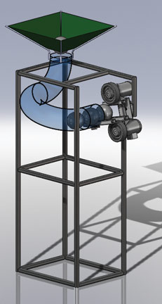
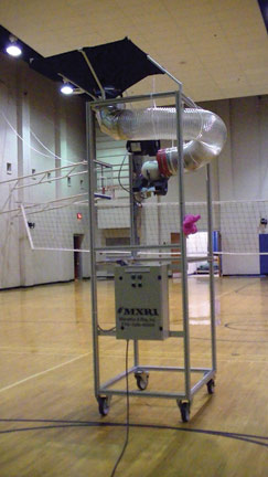
The basic electrical design includes a CLICK PLC controlling two GS drives (VFDs) via Modbus. The GS drives power two small Ironhorse 3-phase motors. The ‘remote control’ consists of a C-more Micro HMI mounted in a handheld enclosure, and tethered to the machine via a long serial cable. The CLICK PLC also controls a series of lights on the front of the machine used to simulate the tossing of the ball into the air (prior to a serve) by a human server. (See Figures 1 & 2 Below)
The mechanical set-up uses two wheel/tire assemblies driven by the Ironhorse motors – one above and one below the volleyball. While the two motors work in concert to determine the overall velocity of the launch, the machine can also impart varying degrees of top-spin to the ball by running the upper motor somewhat faster than the lower motor. Top spin and speed are the primary variables used by volleyball players to vary their serves, and the machine allows a coach to vary both speed and top-spin from the remote control. The mechanical setup also allows for manual adjustments to various angles of the ‘launch head’ delivery mechanism to allow a wide variety of ‘serve’ and ‘set’ simulations.
Research
The team conducted a study of forces that apply to a volleyball in flight using Computational Fluid Dynamics (CFD). The purpose of this study was to predict the path the ball would follow as it flew through the air. CFD calculations were performed using the SolidWorks 2009 CAD software with Flow Simulation package. The coefficient of drag (Cd) and the coefficient of lift (Cl) are the two dimensionless parameters that need to be determined to find the trajectory of the ball in flight. The following formulas show how the coefficients are determined:
Where
Fd = drag force (N)
Fl = lift force (N)
ρ = density of air @ 25° = 1.184kg/m3
V = velocity (m/s)
r = volleyball radius (0.105 m)
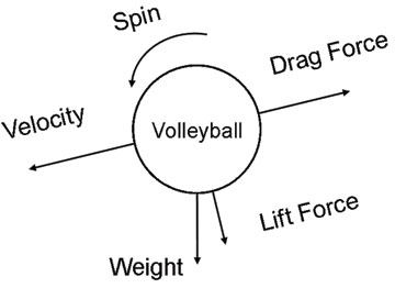
Many CFD studies were performed to calculate the drag force (Fd) and lift force (Fl) acting on the volleyball at various combinations of velocity, spin, and surface roughness. The CFD ‘solver’ was used to determine the forces acting on the ball. These forces were then plugged into Equations 1 and 2 and the coefficients of drag (Cd) and lift (Cl) were calculated. This figure shows a free body diagram of forces acting on the volleyball: (Figure 4)
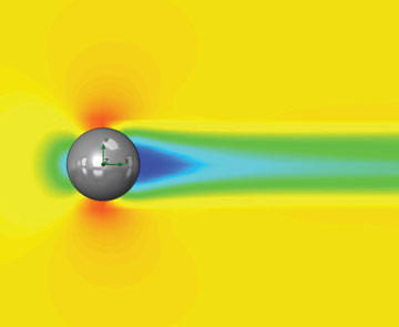
The drag force acts directly opposite to the direction of the velocity vector and the lift force, due to spin, acts perpendicular to it. Some assumptions were made in order to allow for somewhat faster calculations and a simpler CAD model. The surface variations due to the seams were ignored, and the leather surface of the volleyball cover was modeled with a surface roughness of 6μm and 20μm. (Figure 5)
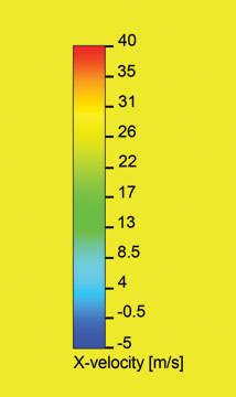
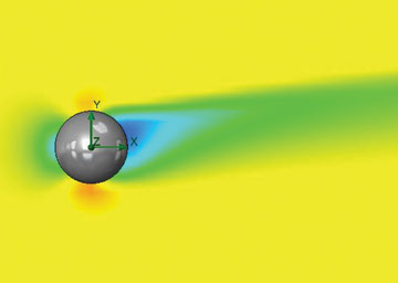
The first flow diagram shows a stagnation point at the front of the ball where the air velocity is very low. On the backside of the ball (dark blue area), some of the air actually moves in the direction of the ball’s motion. The red areas, both above and below the ball, show that the airflow reaches a maximum velocity just above and just below the ball. This is due to the ball having the largest frontal area at that section perpendicular to the air flow.
(Figure 6)
The second flow diagram shows the flow around a spinning volleyball. When the ball has top spin, it resists the air flowing over the top and speeds up the flow under the ball. The red area under the ball is noticeably larger than the red area over the ball. Pressure and velocity are inversely related, so the higher velocity below the ball creates an area of low pressure underneath it. This is the inverse of the familiar airplane wing dynamic which creates the low pressure area on the top of the wing. This means that the spinning ball will encounter a downward ‘lift’ force, which will make it drop faster than a ball that is not spinning. This will come as no surprise to a volleyball player who has ever faced a powerful, overhand (top spin) serve.
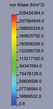
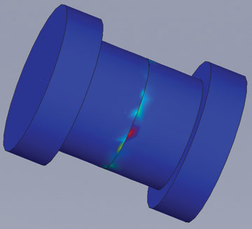
The team also modeled several pressure contours, shear graphs, and flow trajectories. The value for the coefficient of drag (Cd) for all the calculations averaged 0.242. The average value for the coefficient of lift (Cl) for all calculations was 0.466. The team performed a Finite Element Analysis (FEA) on a critical shoulder bolt that holds (and helps to position) the 140 pound launching head assembly. Due to the complex detail of the actual bolt used, a simplier version was created for FEA testing. The static stresses on the bolt were determined to be 65 MPa with a displacement of 0.3 millimeters. The material of the bolt is medium carbon steel with a yield strength of 350 MPa. Since the maximum stress on the bolt is far below the yield strength, this off-the-shelf bolt was deemed acceptable for the application. (Figure 7)
Cost Analysis
The costs for the electrical and mechanical components of the machine totaled less than $3000 for the completion of the prototype, right in line with the prices charged for several commercially available serving machines which do not include the multi-ball hopper or remote control capabilities. Of course the team spent many hours designing and building the prototype, but they believe that with certain refinements their design could be manufactured at a reasonably comparable cost – and sold at a competitive price – to the currently available machines on the market.
Testing
During the initial testing phase, the volleyballs were not launching with as much velocity as the team had anticipated. They determined that the volleyballs were slipping against the wheels in the launching head. The upper wheel was lowered to add more compression to the volleyball, thus increasing the velocity at which the volleyballs were being launched. While this helped, the machine was still not launching balls at realistic competition serving speeds. The team then wrapped the tire surfaces with a much stickier rubber layer to add extra friction, providing the desired launch speeds.
Conclusions
The team was pleased with the performance of the ‘Ace Within Reach’ Volleyball Serving and Setting Machine. The machine was tested by many bystanders during the testing phase and at the team’s final presentation. The repeatability of the machine allowed testers to improve their game by concentrating on a particular placement, speed, and spin of serve. The immediate feedback was very positive. The team has a few ideas for improvements, and they even have a local volleyball club who has eagerly volunteered to spend several weeks testing the machine and to provide detailed feedback. After they receive feedback from the volleyball club, the Ace Within Reach Team wishes to explore the possibilities of patenting and marketing the automatic volleyball serving and setting machine.
As for Larry, this senior design project was the last step required for graduation, and a key step towards his new Engineer position with Hansgrohe. Established in 1901, Hansgrohe designs, manufactures and sells luxury shower, bath and kitchen products. This internationally recognized company is based in Germany and has a U.S. manufacturing headquarters located in Atlanta, Georgia.
By Chip McDaniel
AutomationDirect
Disclaimer: AutomationDirect does not guarantee the products described in this article are suitable for your particular application, nor do we assume any responsibility for your product/system design, installation, or operation.
Originally Published: Dec 1, 2011


